Ultrasonic energy transducer with continuously changed acoustic impedances

An ultrasonic transducer and acoustic impedance technology, applied in ultrasonic/sonic/infrasonic diagnosis, sonic diagnosis, infrasonic diagnosis, etc., can solve the problem of increasing the complexity of ultrasonic transducers, reducing the performance of ultrasonic transducers, and inability to transmit energy, etc. problems, to achieve good acoustic matching effect, multi-layer structure simplification, and the effect of reducing multiple reflections

Inactive Publication Date: 2013-06-12
PHILIPS ULTRASOUND SHANGHAI CO LTD
View PDF0 Cites 2 Cited by
  • Summary
  • Abstract
  • Description
  • Claims
  • Application Information

AI Technical Summary

Problems solved by technology

This not only increases the structural complexity of the ultrasonic transducer, but also causes multiple reflections of sound waves in the bonding layer, thereby reducing the performance of other aspects of the ultrasonic transducer
[0015] 3. Due to the impedance mismatch between the second matching layer and the acoustic lens, some energy cannot be sent to the working medium, and this part of energy will be at the interface between the acoustic lens and the working medium and the interface between the acoustic lens and the second matching layer There are multiple reflections between them. As a result of this multiple reflections, there are obvious near-field bright and dark fringes in the ultrasound imaging system.

Method used


Image

  • Ultrasonic energy transducer with continuously changed acoustic impedances
  • Ultrasonic energy transducer with continuously changed acoustic impedances
  • Ultrasonic energy transducer with continuously changed acoustic impedances

Examples


Embodiment approach

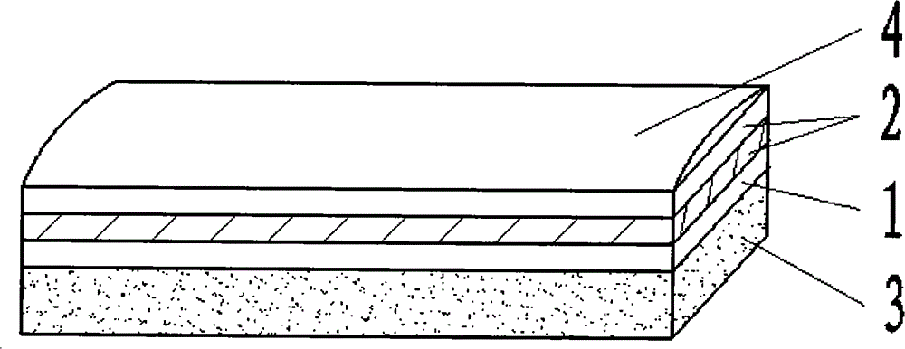
[0038] An ultrasonic transducer with continuously changing acoustic impedance comprises a backing and a piezoelectric material layer which are stacked in sequence, and is characterized in that a layer with continuously varying acoustic impedance is provided between the piezoelectric material layer and the working medium.

[0039] The acoustic impedance continuously changing layer is formed by mixing and solidifying acoustic material particles with the same particle size and different specific gravity and polymer coupling agent.

[0040] Acoustic impedance value Z of the surface adjacent to the layer of continuous acoustic impedance change and the piezoelectric material layer H It is equal to the acoustic impedance value of the piezoelectric material layer, and the acoustic impedance value Z of the surface adjacent to the working medium of the continuous acoustic impedance change layer l It is equal to the acoustic impedance value of the working medium.

Embodiment 1

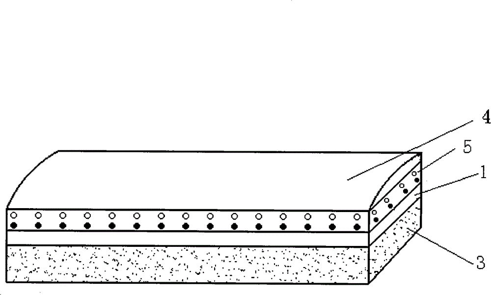
[0042] In this embodiment, the ultrasonic transducer is not in direct contact with the working medium, and a lens layer is added.

[0043] see figure 2 , an ultrasonic transducer with continuously varying acoustic impedance, comprising a backing 3 , a piezoelectric material layer 1 , a continuously varying acoustic impedance layer 5 and a lens layer 4 which are stacked in sequence.

[0044] The acoustic impedance continuously changing layer 5 is formed by mixing and solidifying acoustic material particles with the same particle size and different specific gravity and polymer coupling agent.

[0045] To prepare a non-conductive acoustic impedance continuously variable layer 5, the piezoelectric material layer 1 can be selected as the material of the high impedance end of the acoustic impedance continuously variable layer 5, and its acoustic impedance value is ZH , select the hollow non-metallic material as the material of the low impedance end of the acoustic impedance continu...

Embodiment 2

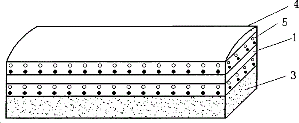
[0053] see image 3 The difference between the second embodiment and the first embodiment is that a material layer with continuously changing acoustic impedance is also arranged between the backing 3 and the piezoelectric material layer 1, and the surface of the material layer with continuously changing acoustic impedance is adjacent to the backing 3 The acoustic impedance value of is equal to the acoustic impedance value of the backing 3, and the acoustic impedance value of the surface of the continuously changing acoustic impedance material layer adjacent to the piezoelectric material layer 1 is equal to the acoustic impedance value of the piezoelectric material layer 1. Similarly, the acoustic impedance of the continuously changing acoustic impedance material layer is continuously distributed along the longitudinal direction, the preparation method of the continuously changing acoustic impedance material layer is the same as the preparation method of the continuously changin...


PUM


Abstract

The invention relates to an ultrasonic energy transducer with continuously changed acoustic impedances, which comprises a bake lining and a piezoelectric material layer which are sequentially overlapped, wherein an acoustic impedance continuous change layer is arranged between the piezoelectric material layer and a working medium. The ultrasonic energy transducer with continuously changed acoustic impedances can realize the acoustic matching among different acoustic impedances by only one acoustic impedance continuous change layer so as to ensure that the structure of the ultrasonic energy transducer is greatly simplified, and multiple reflection among structure layers does not exist, thereby improving the emission efficiency of acoustic energy.

Description

technical field [0001] The invention relates to an ultrasonic transducer, in particular to an ultrasonic transducer whose acoustic impedance changes continuously. Background technique [0002] Ultrasonic transducer is a passive, passive two-way transducer that converts electrical signals into acoustic signals, sends them to the working medium, and then converts the acoustic signals transmitted, scattered or reflected back through the working medium into electrical signals. device. The performance of the ultrasonic transducer is a key device that determines the performance of the corresponding system. [0003] Such as figure 1 As shown, the prior art ultrasonic transducer includes a piezoelectric material layer 1, a matching layer 2, a backing 3 and an acoustic lens 4. In order to make the ultrasonic transducer have a higher electromechanical efficiency, the ultrasonic transducer usually adopts Two or more matching layers make the piezoelectric material layer 1 with high a...

Claims


Application Information

Patent Timeline
Patent Type & Authority Patents(China)
IPC IPC(8): A61B8/00
Inventor 袁建人
Owner PHILIPS ULTRASOUND SHANGHAI CO LTD
Why Eureka
Try Eureka