
Ejector of a movable furniture part

一种家具部件、推出器的技术,应用在家具零件、翼扇部件、家里用具等方向

Active Publication Date: 2013-09-18
JULIUS BLUM GMBH
View PDF1 Cites 0 Cited by
  • Summary
  • Abstract
  • Description
  • Claims
  • Application Information

AI Technical Summary

Problems solved by technology

Such a device can therefore only be used to a limited extent in connection with movable furniture parts which are supported in or on the furniture body in such a way that the movable furniture part only protrudes or doesn't even reach into the concrete

Method used


Image

  • Ejector of a movable furniture part
  • Ejector of a movable furniture part
  • Ejector of a movable furniture part

Examples


Embodiment Construction

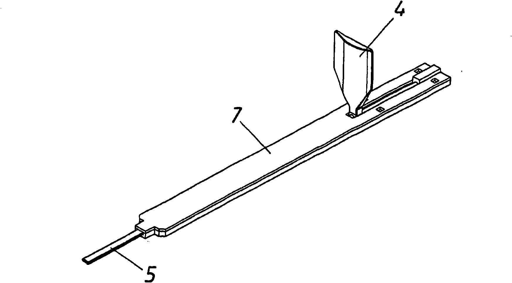
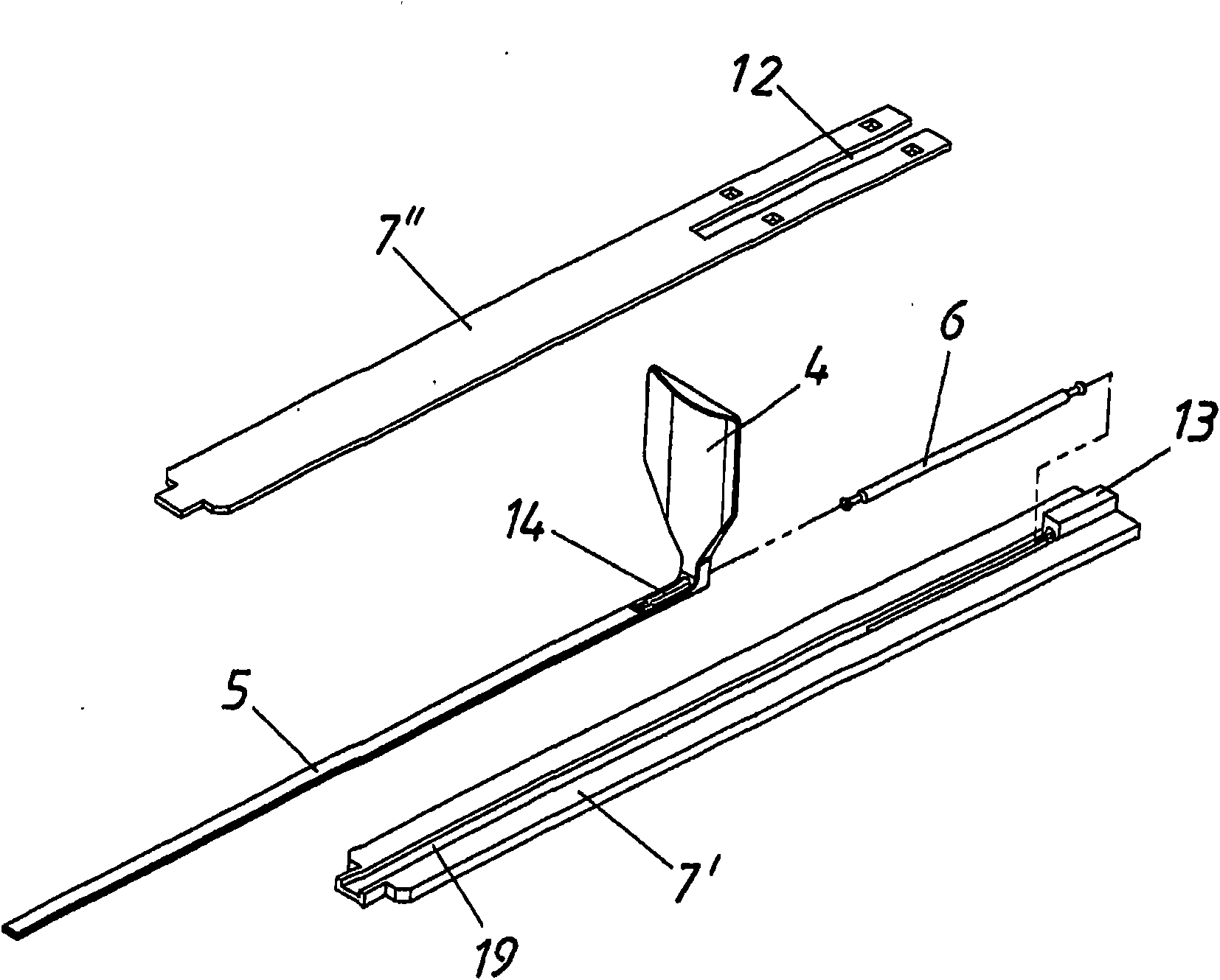
[0036] exist Figure 1a The structure of an embodiment of the force transmission device is shown in . A housing 7 can be seen in which a plunger 5 is guided in a channel 19 . The plunger 5 is partially removable from the housing 7 and is connected in one piece to a stop 4 in the exemplary embodiment. as in particular by Figure 1b It can be seen that the housing 7 consists of a base plate 7 ′ and a cover 7 ″. The cover 7 ″ has a slot 12 which allows the movement of the stop 4 arranged on the plunger 5 . The plunger 5 and the stop 4 are thus biased by an energy store 6 (here a helical spring) in such a way that the energy store 6 attempts to move the plunger 5 back into the housing 7 . The energy store 6 is supported on one side on a support element 13 and is connected to the plunger 5 on the other side. The plunger 5 has here at its rear end a recess 14 for receiving one end of the energy store 6 .

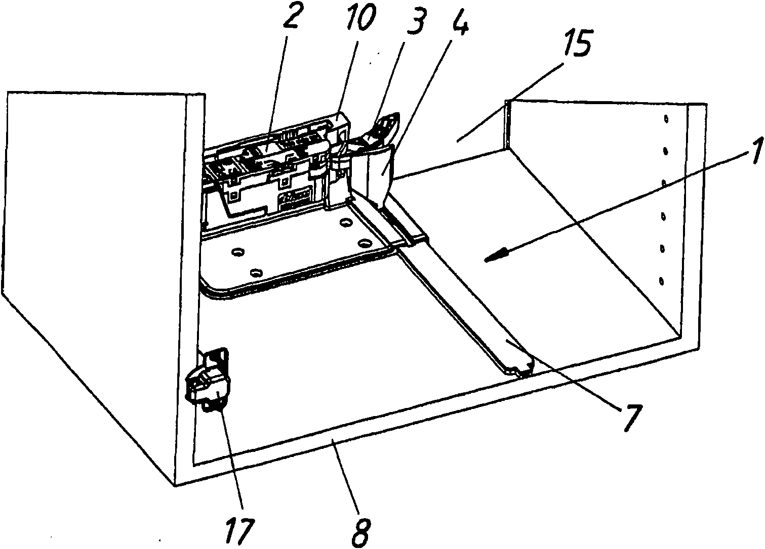
[0037] Figure 2a The furniture body 8 of a piece of furniture is shown ...


PUM


Abstract

A device for ejecting a movable furniture part from a closed end position in or on a furniture body, includes an ejector with a motor-driven ejector lever. A power transmission device interacting with the ejector lever is provided such that the force exerted on the movable furniture part by the ejector lever can be transferred in the mounted state of the device in a furniture body, in which the movable furniture part in the closed end position is at a distance from the ejector lever.

Description

technical field [0001] The invention relates to an ejection device for ejecting a movable furniture part from a closed end position in or on a furniture body. The invention also relates to a piece of furniture comprising the push-out device and a force transmission device for the push-out device. Background technique [0002] Such devices have hitherto essentially consisted only of an ejector whose electrically driven ejector lever bears loosely against the movable furniture part in its closed end position. Such a device can therefore only be used to a limited extent in connection with movable furniture parts which are supported in or on the furniture body in such a way that the movable furniture part only protrudes or Doesn't even reach into the concrete of the home. Examples of such furniture parts are furniture doors and lids as well as drawers whose depth is significantly smaller than the depth of the furniture body. Contents of the invention [0003] It is therefor...

Claims


Application Information

Patent Timeline
Patent Type & Authority Patents(China)
IPC IPC(8): A47B88/04
CPCE05Y2900/20E05Y2201/426E05Y2201/434A47B88/0477E05F15/147A47B88/457A47B88/463E05Y2201/686E05F15/649
Inventor K·布吕斯特勒
Owner JULIUS BLUM GMBH
Learn More