

Radial feed mechanism
A feeding mechanism and tool feeding technology, which is applied to metal processing machinery parts, boring machine/drilling machine parts, metal processing equipment, etc., can solve the problem of poor rigidity, short stroke, inability to process large end faces of inner holes of box parts, etc. question
Inactive Publication Date: 2011-01-05
吴淼东
View PDF1 Cites 0 Cited by
- Summary
- Abstract
- Description
- Claims
- Application Information
AI Technical Summary
Problems solved by technology
Due to the short stroke and poor rigidity of the radial feed of this mechanism, it cannot be adapted to process the wider and deeper grooves in the inner hole of the box part, nor can it process the large end surface of the inner hole of the box part.
Method used
View moreImage
Smart ImageViewing Examples

Examples
Embodiment Construction
Login to View More PUM
 Abstract
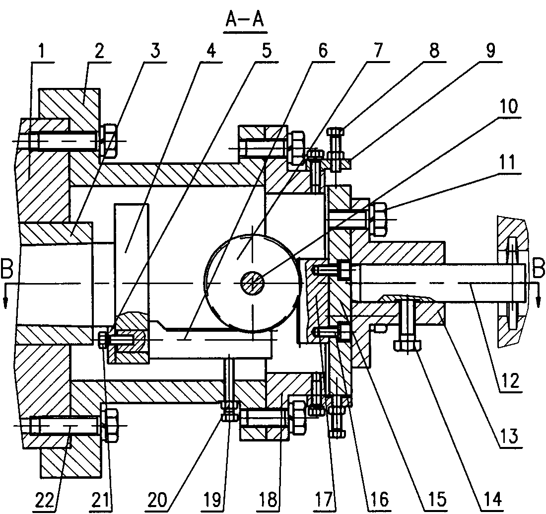
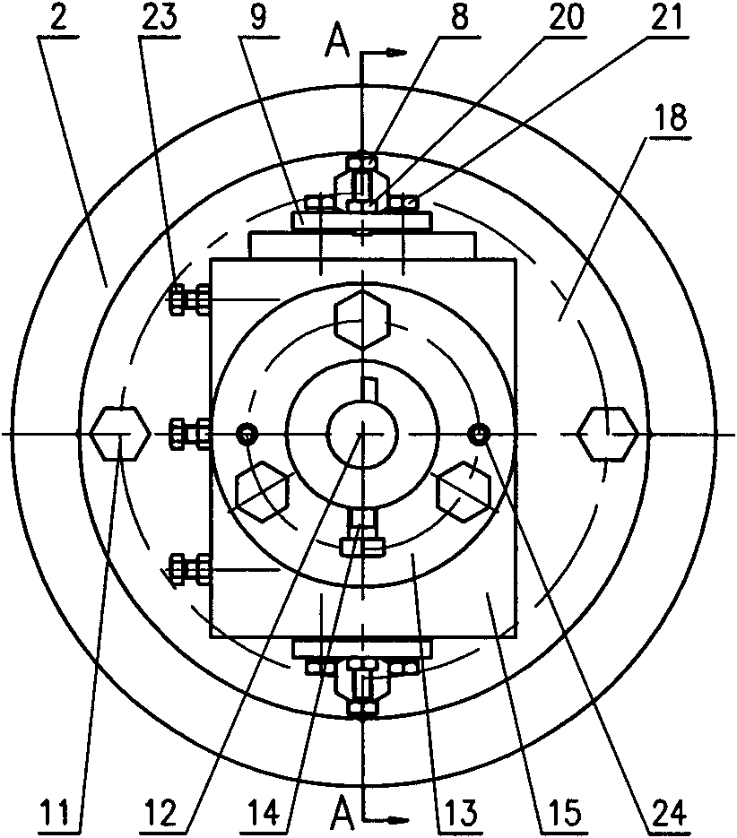
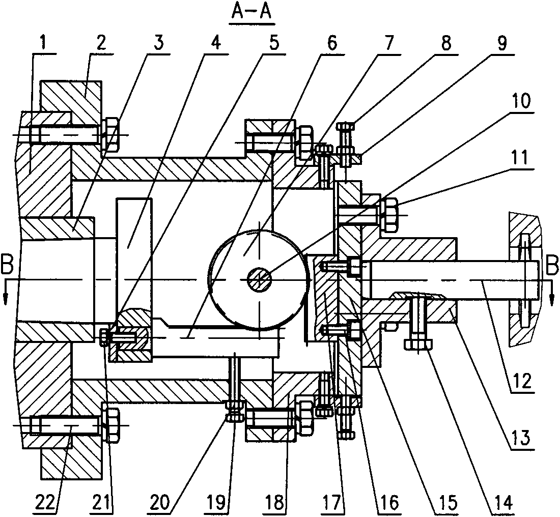
The invention discloses a radial feed mechanism. A support is fixed on the front end of the main shaft of a boring lathe, a slide carriage seat is fixed on the support, a slide carriage is matched with the slide carriage seat by a dovetail groove, and a fit clearance between the slide carriage and the slide carriage seat is adjusted by an inserted bar; a cutting feed shaft is arranged in a taper hole on the front end of a boring lathe boring bar; an axial rack is arranged on a disk on the front end of the cutting feed shaft; a gear is arranged on the slide carriage seat by a mandrel to be meshed with the axial rack; a radial rack is fixed on the slide carriage to be meshed with the gear; the slide carriage seat is provided with a positioning mechanism which can limit the slide carriage tomove, and the movement direction of the slide carriage is vertical to the rotary axis of the boring lathe; the cutter seat is fixed on the slide carriage, and the cutter is fixed on the cutter seat. The boring bar moves, and the axial rack drives the gear to rotate, so that the radial rack drives the slide carriage to move to realize radial feeding. When used, the radial feed mechanism can conveniently and economically process wider and deeper grooves in the inner bore of the part of a box body and the high-precision end surface in the inner bore of the part of the box body. The invention is especially suitable for mass production of parts.
Description
radial feed mechanism technical field The invention relates to technological equipment for processing mechanical parts, especially a radial feed mechanism. Background technique In mechanical manufacturing, there are grooves that need to be processed in the inner holes of some box parts, which are not suitable for processing on a lathe. When machining on a boring machine, the boring tool is required to have the function of radial feed. On the boring machine to process the box body parts and the large end face with high position accuracy of the boring inner hole, it is easy to ensure the machining accuracy by using the radial feed method of the boring tool. This requires the boring machine to have a radial feed mechanism. At present, some boring machines do not have such a mechanism. Even if some boring machines have a radial feed mechanism, for mass production, it is troublesome to replace the mechanism. If the matching mechanism is not designed, the efficiency of process...
Claims
Login to View More Application Information
Patent Timeline
 Patent Type & AuthorityPatents(China)
IPC IPC(8): B23Q5/34B23B47/00
Inventor刘家峰吴淼东
Owner吴淼东