Improved structure of polyurethane elastomer casting machine

A polyurethane elastomer and pouring machine technology, applied in the field of pouring machines, can solve the problems of difficult to observe the flow of internal raw materials, overloaded controllers, poor thermal insulation effect of accessories, etc., achieving significant energy saving effect, reducing continuous heating, and reducing heat dissipation. Effect

Active Publication Date: 2009-12-23
ZHEJIANG TIANTAI XIANGHE IND CO LTD
View PDF0 Cites 14 Cited by
  • Summary
  • Abstract
  • Description
  • Claims
  • Application Information

AI Technical Summary

Problems solved by technology

[0002] At present, the structure of the polyurethane elastomer pouring machine generally includes a controller, two material tanks connected to the controller, a heater, an agitator connected to the feeding pipe of the material tank, and a molding die: the material tank generally All have an interlayer, and use a heater outside the material tank to heat the interlayer so as to heat the raw materials in the material tank to the required temperature. The disadvantages are: first, the insulation effect of the pipeline and accessories at the lower part of the material tank is poor , the temperature is lost quickly, and the heater needs to provide a large amount of heat energy for heating, which wastes heat energy. The burden on the controller is too heavy; the forming mold generally includes an upper mold and a lower mold, and the mixed resin is injected into the lower mold to close the mold, and the mold is opened after it is foamed and solidified. The disadvantages are: During the process of mold closing, there will be air bubbles left in the mold, causing air holes on the upper or lower surface of the foamed finished product, which will affect the appearance of the product and the strength of the product; the agitator generally does not Set up a cooling and cooling device, and the temperature of the raw materials transported from the material tank is generally maintained at about 90°C. At this temperature, the two raw materials will foam when they are not stirred and mixed evenly, and they must wait for cooling to a suitable temperature ( Stirring can only be carried out after about 50°C). In this way, it is not easy to control, and the waiting time is long, which affects the production efficiency; in addition, the current feeding pipe: first, it is equipped with an insulation layer, which increases the cost of the equipment and makes it difficult to observe the inside The flow of raw materials; the second is that the diameter of the pipe is large. When the shutdown or power failure occurs, more raw materials will be left in the pipeline, resulting in waste of raw materials and increased production costs.

Method used


Image

  • Improved structure of polyurethane elastomer casting machine
  • Improved structure of polyurethane elastomer casting machine
  • Improved structure of polyurethane elastomer casting machine

Examples


Embodiment Construction

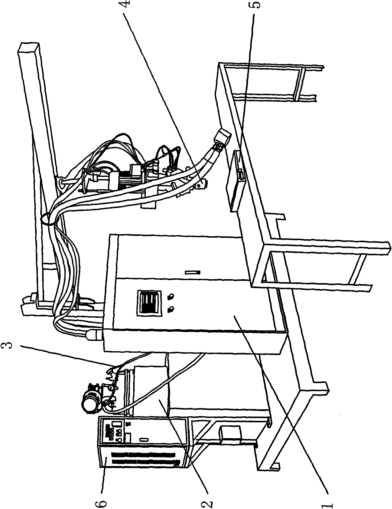
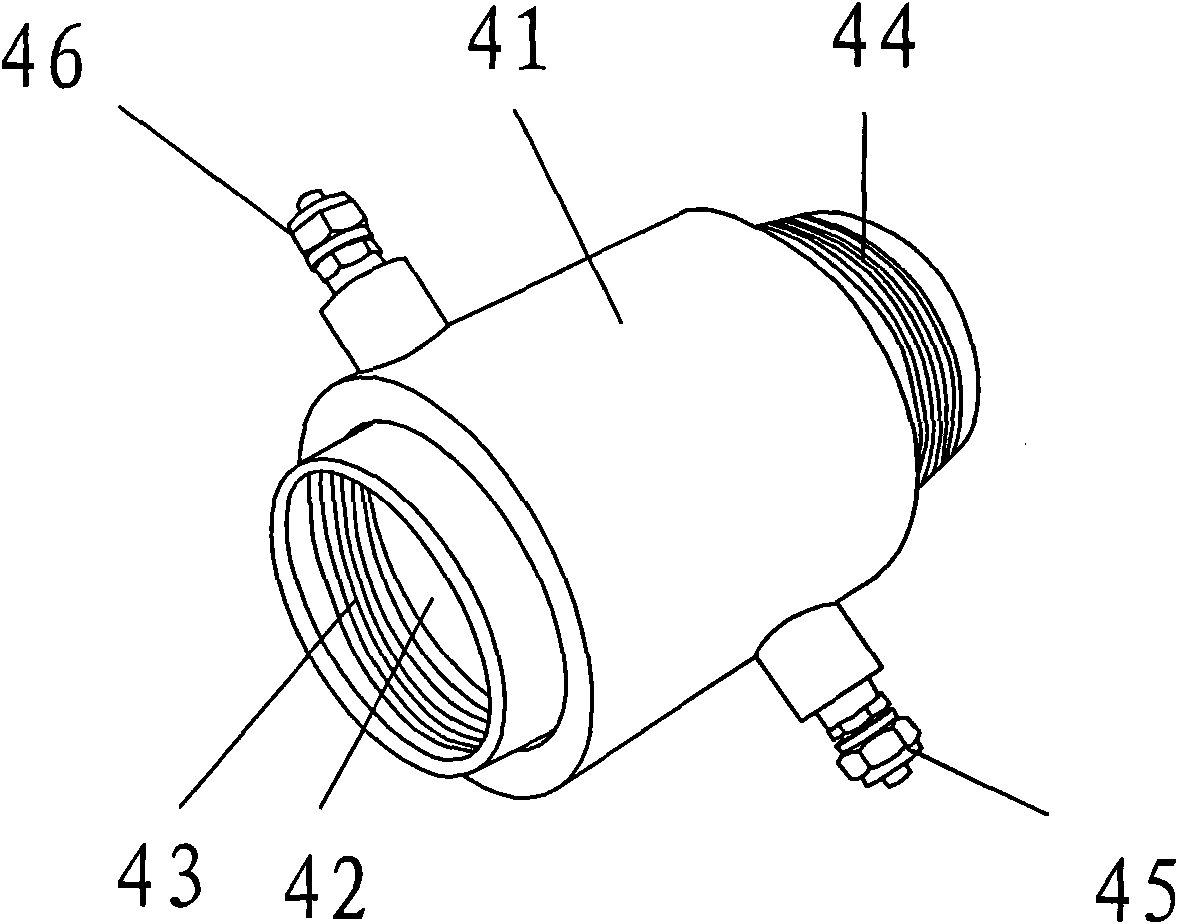
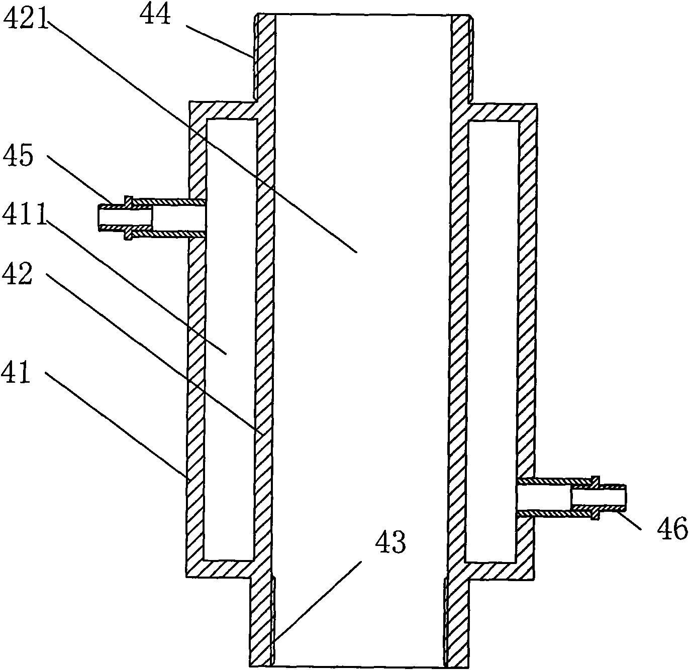
[0023] The present invention will be further described below with specific embodiment, see Figure 1-7 :

[0024] The structural improvement of the polyurethane elastomer pouring machine includes a controller 1, a material tank 2 connected to the controller 1, a heater 6, an agitator 4 connected to the feed pipe 3 of the material tank 2, and a molding die 5. The material tank 2 described is: the bottom of the material tank 2 is provided with an incubator 21 that wraps the bottom equipment of the material tank, and the heating device 23 controlled by the heater 6 is arranged in the incubator 21; the agitator 4 described is; The outer surface of the agitator housing 42 is covered with a jacket 41 for filling the cooling medium, and the side of the jacket 41 is provided with cooling medium inlets and outlets 45, 46 communicated with the inner cavity 411 between the housing 42 and the jacket 41 , the raw material is stirred by the stirring head in the inner cavity 421 of the hous...


PUM


Abstract

The invention belongs to the technical field of casting machines, in particular to an improved structure of a polyurethane elastomer casting machine, comprising a controller, a charging bucket and a heater which are both connected with the controller, a stirrer connected with the feed delivery pipe of the discharge bucket and a forming mold. The lower part of the discharge bucket is provided with an insulated cabinet wrapping the lower devices of the discharge bucket; the external surface of a stirrer casing is provided with an external sleeve for charging cooling medium in a sleeving way; the side wall of the forming mold is provided with an opening and articulated with a side cover; and the feed delivery pipe adopts a thin plastic pipe without a heater. The improved structure of the polyurethane elastomer casting machine has the advantages of remarkable heat insulation and energy-saving effects, reduction of the cooling time of raw materials in the stirrer, improvement of production efficiency, attractive shape, consistent strength, saving of the raw materials and waste reduction due to the thin plastic pipe used as the feed delivery pipe and improvement of the production benefits of an enterprise, and is suitably applied to polyurethane elastomer casting machines of the same type.

Description

technical field [0001] The invention belongs to the technical field of pouring machines, in particular to a structural improvement of a polyurethane elastomer pouring machine. Background technique [0002] At present, the structure of the polyurethane elastomer pouring machine generally includes a controller, two material tanks connected to the controller, a heater, an agitator connected to the feeding pipe of the material tank, and a molding die: the material tank generally All have an interlayer, and use a heater outside the material tank to heat the interlayer so as to heat the raw materials in the material tank to the required temperature. The disadvantages are: first, the insulation effect of the pipeline and accessories at the lower part of the material tank is poor , the temperature is lost quickly, and the heater needs to provide a large amount of heat energy for heating, which wastes heat energy. The burden on the controller is too heavy; the forming mold generally...

Claims


Application Information

Patent Timeline
Patent Type & Authority Applications(China)
IPC IPC(8): B29C39/00B29C39/22B29C39/38B29C39/26B29C39/44B29K75/00
Inventor 汤啸
Owner ZHEJIANG TIANTAI XIANGHE IND CO LTD
Why Eureka
Try Eureka