High-brightness LED underwater energy saving lamp

An LED underwater light, high-brightness technology, which is used in gas/waterproof devices, lighting devices, cooling/heating devices for lighting devices, etc. problems, to achieve the effect of improving the light conversion efficiency, increasing the contact area, and prolonging the service life

Inactive Publication Date: 2009-12-23
杭州亿奥光电有限公司
View PDF2 Cites 57 Cited by
  • Summary
  • Abstract
  • Description
  • Claims
  • Application Information

AI Technical Summary

Problems solved by technology

Its shortcomings: First, because the heat generated by the light-emitting board composed of multiple LED chips is concentrated on the light-emitting board, whether the temperature of the light-emitting board can be reduced does not depend on the heat conduction relationship between the light-emitting board itself and the shell, but on the It depends on the electric fan and air in the cavity of the lamp seal lampshade
Since the air in the lampshade is limited and is heated by the heat generated by the luminous panel itself, the electric fan inside the lampshade acts on the luminescent panel instead of cool wind but hot air, which cannot effectively reduce the heat of the luminescent panel. As a result, the light-to-heat conversion efficiency of the light-emitting panel is low and the energy consumption is high; secondly, because the electric fan is in a high-temperature sealed cavity, the heat generated during its operation can only form convection with the hot air in the sealed cavity, so the electric fan is very easy to damage
If the electric fan is damaged, the heat on the luminous board cannot form convection, and the LED chip in the luminous board cannot work normally. When the temperature of the luminous board is higher than the rated normal operating temperature of the LED chip, the LED chip in the luminous board will be damaged.

Method used


Image

  • High-brightness LED underwater energy saving lamp
  • High-brightness LED underwater energy saving lamp
  • High-brightness LED underwater energy saving lamp

Examples


Embodiment 1

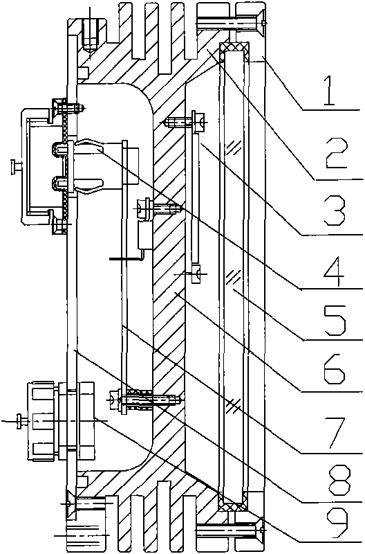
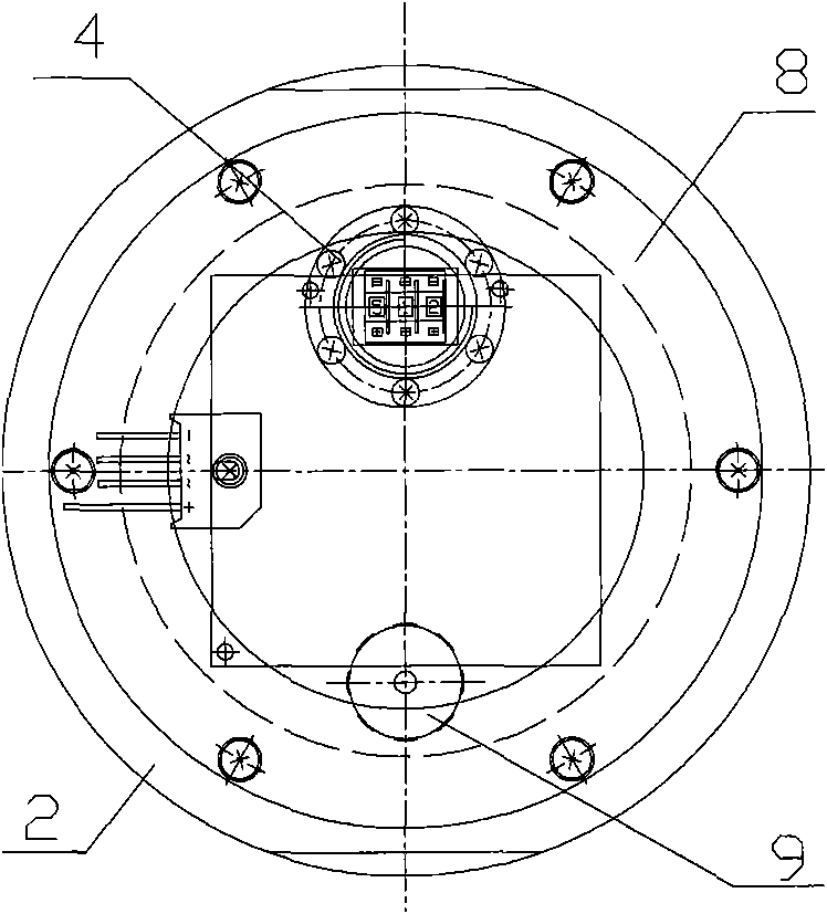
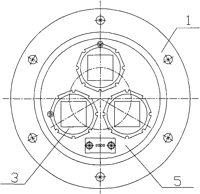
[0010] Embodiment 1: with reference to attached Figure 1~3 . High-brightness LED underwater light, the double-sided grooved lamp housing 2 is a metal shell, the double-sided grooved lamp housing 2 has one or more LED chips 3 on the grooved surface 6, and the transparent cover 5 is located on both sides The side of the recessed lamp housing 2 that is equipped with LEDs is waterproof and sealed with the rubber sealing ring. The other groove cavity of the double-sided recessed lamp housing 2 is equipped with a control circuit board 7 and the signal terminal of the control circuit board 7 Connect to the signal end of one or more LED chips 3 respectively, the terminal 4 is sealed and connected to the sealing cover plate 8 and the lead wire of the terminal 4 is connected to the signal end of the control circuit board 7, the sealing cover plate 8 is connected to the double-sided groove type The other side of the lamp housing 2 is hermetically fitted, and the outside of the double-s...

Embodiment 2

[0011] Embodiment 2: On the basis of Embodiment 1, when the connection terminal 4 is a data connection terminal, the power connection terminal 9 is sealed and connected to the sealing cover plate 8 and the lead wire of the power connection terminal 9 is connected to the control circuit board 7 power supply end.


PUM


Abstract

The invention relates to a high-brightness LED underwater lamp with low energy consumption and numerically controlled light color. A groove surface of a double-sided groove type lamp housing is provided with one or more LED chips. A transparent cover is arranged on and matched with one side, where an LED is arranged, of the double-sided groove type lamp housing by a rubber sealing ring in a waterproof sealed manner. Another groove cavity of the double-sided groove type lamp housing is internally provided with a control circuit board, a signal end of which is respectively connected with signal ends of one or more LED chips. A wiring terminal is sealed and connected on a sealing cover plate and a lead of the wiring terminal is connected with the signal end of the control circuit board. The sealing cover plate is sealed and matched with the other side of the double-sided groove type lamp housing. The energy saving lamp has the advantages of firstly, not only avoiding unfavorable effect of the control circuit board on the LED chip, but also considerably improving the optical conversion efficiency of the LED chip; secondly, realizing the direct temperature reduction to the LED chip, decreasing energy consumption, improving the optical conversion efficiency of the LED chip and considerably prolonging the service life of the LED chip; and thirdly, realizing the purpose of direct water-cooled temperature reduction.

Description

technical field [0001] The invention relates to a high-brightness LED underwater energy-saving lamp with high brightness, low energy consumption and digitally controlled light color, which belongs to the field of manufacturing underwater lighting lamps. Background technique [0002] Authorized announcement number CN 201072114Y, name "temperature-controlled high-power LED underwater light", including a lampshade, lamp body and control circuit, the lampshade and lamp body form a sealed whole, the control circuit includes a driving power supply and a plurality of LED The light-emitting board composed of chips, the light-emitting board is installed in the lamp body, and the lamp body is divided into an upper chamber and a lower chamber that communicate with each other, the driving power is fixed at the bottom of the lamp body, and the bottom of the lamp body is located below the light-emitting board. Connect with the control circuit through wires. Its shortcomings: First, becau...

Claims


Application Information

Patent Timeline
Patent Type & Authority Applications(China)
IPC IPC(8): F21V23/00F21V23/06F21V31/00F21V29/00F21Y101/02F21V29/507F21V29/56F21Y115/10
Inventor 蔡勇
Owner 杭州亿奥光电有限公司
Why Eureka
Try Eureka