
A method for horizontal calibration of surface converted wave data using vsp converted wave data

A technology for converting waves and data, which is applied in the field of ground-converted wave data horizon calibration, which can solve the problems of inability to directly compare, difficult time-depth relationship, and inconspicuous geological structure characteristics, and achieve the effect of improving the production accuracy.

Inactive Publication Date: 2011-12-07
中国石化集团胜利石油管理局有限公司
View PDF0 Cites 0 Cited by
  • Summary
  • Abstract
  • Description
  • Claims
  • Application Information

AI Technical Summary

Problems solved by technology

Since the converted wave velocity V PS less than the longitudinal wave velocity V P , so the two-way travel time of the converted wave at the same reflection interface is greater than that of the longitudinal wave, so it cannot be compared directly
[0003] At present, the horizon interpretation of converted wave seismic data is mainly carried out according to the corresponding relationship of wave groups in the P-wave and S-wave sections (namely, the phase plane method), that is, in the P-wave and converted-wave sections, some wave groups with obvious characteristics are obtained. It is used as a reference for comparison; or people usually use converted-wave artificially synthesized records, combined with the corresponding structural features on the P-wave and converted-wave profiles, to directly calibrate the converted-wave horizon, but the above methods are often difficult to accurately determine the To determine the required time-depth relationship, the method of using artificial synthetic records to directly calibrate the horizon of ground converted wave data has the following problems: the production accuracy of converted wave synthetic records is not high, and the accurate horizon of ground converted wave seismic data cannot be realized calibration

Method used


Image

  • A method for horizontal calibration of surface converted wave data using vsp converted wave data
  • A method for horizontal calibration of surface converted wave data using vsp converted wave data
  • A method for horizontal calibration of surface converted wave data using vsp converted wave data

Examples


Embodiment Construction

[0026] In order to make the object, technical solution and advantages of the present invention clearer, the present invention will be described in detail below with reference to the accompanying drawings and examples.

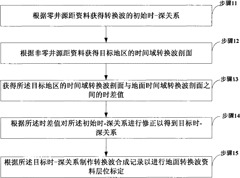
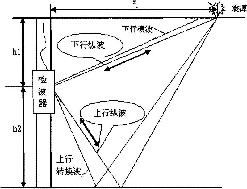
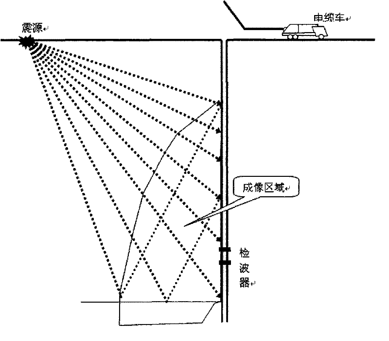
[0027] The method of utilizing VSP converted wave data to carry out horizon calibration of surface converted wave data provided by the present invention utilizes the zero-well-source-spacing (zero-bias) data and non-zero-well-source-spacing (non-zero-bias) data of the vertical seismic section data simultaneously, That is, firstly, the initial time-depth relationship is obtained according to the zero well source distance data, and then the actual surface seismic converted wave profile is compared with the converted wave profile in the target area obtained from the non-zero well source distance data to obtain the time difference, and finally the time difference is used to analyze the Correct the initial time-depth relationship obtained from the zero-well source-sp...


PUM


Abstract

The invention discloses a method for calibrating the horizon of surface converted wave data using VSP converted wave data, including: A. obtaining the initial time-depth relationship of converted waves according to the zero well-source distance data; B. according to the non-zero well-source distance The data obtains the time domain converted wave profile of the target area; C, obtains the time difference value between the time domain converted wave profile of the target area and the ground time domain converted wave profile; D, according to the time difference value to the initial The time-depth relationship is corrected to obtain the target time-depth relationship; E. According to the target time-depth relationship, the converted wave synthetic record is made to carry out the horizon calibration of the ground converted wave data. This method can improve the production accuracy of converted wave synthetic records, and can more accurately calibrate surface converted wave seismic data when interpreting ground multi-wave and multi-component seismic data.

Description

technical field [0001] The invention belongs to the field of seismic data interpretation, in particular to a method for calibrating the horizon of ground converted wave data by using VSP (Vertical Seismic Profiling, vertical seismic profile) data. Background technique [0002] Converted-wave horizon calibration is a difficult and important point in the interpretation of surface multi-wave and multi-component seismic data. Since the converted wave velocity V PS less than the longitudinal wave velocity V P , so the two-way travel time of the converted wave on the same reflection interface is greater than that of the longitudinal wave, so it cannot be compared directly. [0003] At present, the horizon interpretation of converted wave seismic data is mainly carried out according to the corresponding relationship of wave groups in the P-wave and S-wave sections (namely, the phase plane method), that is, in the P-wave and converted-wave sections, some wave groups with obvious c...

Claims


Application Information

Patent Timeline
Patent Type & Authority Patents(China)
IPC IPC(8): G01V1/28
Inventor 王秀玲林松辉刘玉珍李九生余鹏
Owner 中国石化集团胜利石油管理局有限公司
Learn More