Instantaneous remote-sensing polarization imaging device based on microwave plate array and realizing method thereof

A technology of microwave plate array and polarization imaging, which is applied in the direction of measuring the polarization of light, measuring devices, and reradiation of electromagnetic waves, etc., which can solve the problems of inability to measure the S3 component of the optical rotation component, difficult pixel level of the image, and low spatial resolution. , to facilitate coating and maintenance, optimize performance, and improve imaging quality

Inactive Publication Date: 2015-08-12
FUZHOU UNIV
View PDF5 Cites 23 Cited by
  • Summary
  • Abstract
  • Description
  • Claims
  • Application Information

AI Technical Summary

Problems solved by technology

At present, the temporal and spatial resolution of framing and sub-aperture polarization imaging is high, but the optical path is complex, the stability is insufficient, and it is difficult to align images of different polarization states at the pixel level; Group modulation image polarization state, the existence of interference fringes leads to low spatial resolution; the split focal plane scheme can realize polarization state measurement through a single exposure, and the overall system is compact in structure and stable in performance. It has been used in the radar remote sensing of the US military System is the future development direction of polarization imaging technology
However, at present, the focal plane polarization imaging based on the micropolarizer array can only measure the first three components (S0, S1, S2) of the Stocks vector. The reason is that the S3 component representing the optical rotation component cannot be measured by simply changing the direction of the polarizer.

Method used


Image

  • Instantaneous remote-sensing polarization imaging device based on microwave plate array and realizing method thereof
  • Instantaneous remote-sensing polarization imaging device based on microwave plate array and realizing method thereof
  • Instantaneous remote-sensing polarization imaging device based on microwave plate array and realizing method thereof

Examples


Embodiment Construction

[0024] The present invention will be further described below in conjunction with the accompanying drawings and embodiments.

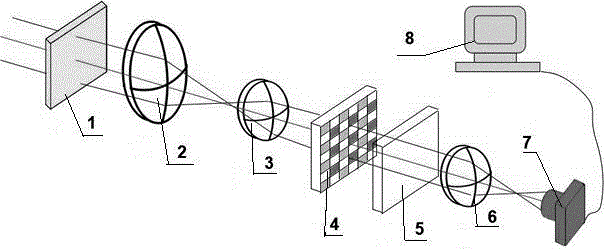
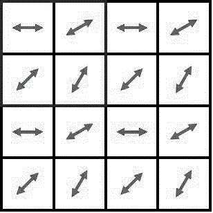
[0025] Such as figure 1 As shown, the present embodiment provides a kind of instantaneous remote sensing polarization imaging device based on a microwave plate array, including a telescope objective lens, a telescope eyepiece, an imaging lens, and an array camera arranged side by side from left to right; the front of the telescope objective lens is arranged There is a narrow-band filter for selecting a specific bandwidth; a microwave plate array and a unidirectional polarizer are sequentially arranged between the telescope eyepiece and the imaging lens, wherein the microwave plate array is arranged on the telescope eyepiece The focal length position is used to modulate the polarization state of the image, and the unidirectional polarizer is arranged between the microwave plate array and the imaging lens to convert the two-dimensional polarization state ...


PUM


Abstract

The invention relates to an instantaneous remote-sensing polarization imaging device based on a microwave plate array and a realizing method thereof. The microwave plate array is used for performing polarization modulation on a remote sensing image which is acquired by a telescope. Then the remote sensing image is converted to two-dimensional light intensity distribution through a unidirectional polaroid. Data inversion is performed on the two-dimensional light intensity for obtaining the polarization information of the remote sensing image. The used microwave plate array is manufactured through ultrafast laser microprocessing. Four different kinds of phase modulations are introduced to each micro area of the image. After the polarization information is converted to the light intensity through the polaroid, the Stocks vector of the area can be calculated, thereby obtaining the complete polarization information of the whole image. The instantaneous remote-sensing polarization imaging device can perform dynamic target remote-sensing measurement, and furthermore realizes complete polarization measurement with high time resolution and high space resolution.

Description

technical field [0001] The invention relates to the application field of optical polarization state measurement, in particular to an instantaneous remote sensing polarization imaging device based on a microwave plate array and a realization method thereof. Background technique [0002] Polarization imaging technology refers to the technology of recording the polarization information of images. The polarization state of the image can provide a lot of information that cannot be obtained from the spectrum, light intensity, coherence, etc., including surface features, shape, shadow, and roughness. Therefore, the polarization imaging technology can be used to distinguish and characterize the target. In meteorological and environmental scientific research, use the polarization characteristics of cirrus scattered radiation to obtain its microscopic and optical characteristics, which provides an important basis for the study of global radiation balance and climate change; in the...

Claims


Application Information

Patent Timeline
Patent Type & Authority Applications(China)
IPC IPC(8): G01S17/00G01S7/481G01J4/00
CPCG01S17/00G01J4/00G01S7/481
Inventor 许灿华马靖裴丽燕邱鑫茂施洋
Owner FUZHOU UNIV
Why Eureka
Try Eureka