Driving device and method

A driving device and driving method technology, applied in motor control, sustainable manufacturing/processing, electrical components, etc., can solve the problems of increased design time and cost, inability to integrate, design difficulty, etc., to shorten the detection and response time, Improve work efficiency, save design cost and time

Inactive Publication Date: 2009-12-23
ELAN MICROELECTRONICS CORPORATION
View PDF0 Cites 7 Cited by
  • Summary
  • Abstract
  • Description
  • Claims
  • Application Information

AI Technical Summary

Problems solved by technology

The traditional pulse width modulation drive device 10 unidirectionally gives the pulse width modulation signal PWM to control the speed of the motor 12, but the motor 12 does not return any information to the drive device 10. Generally speaking, the higher the speed of the motor 12 , the greater the current on it, but abnormalities may occur in some cases, for example, when an electric locomotive is traveling on an uphill slope, the speed of the motor 12 will be affected at this time, so when the motorcyclist wants to speed up the speed of the motor 12 to speed up When the vehicle speed is high, there may be an abnormal situation that the motor 12 rotates at a constant speed but the current on the motor 12 increases. In order to avoid damage to the motor 12 due to an abnormal state, the traditional method is to detect the current on the motor 12 with a Hall element 14, and continuously The current information is transmitted to the drive device 10 so that the drive device 10 can handle it when the condition of the motor is abnormal
[0003] However, the Hall element 14 can only be hung on the outside of the drive unit 10 and cannot be integrated into it, which causes difficulty in design, increases design time and cost, and complicates programming.
Furthermore, since the Hall element 14 is separated from the driving device 10, it takes a long time from when the Hall element 14 detects an abnormality to when the driving device 10 starts to respond.

Method used


Image

  • Driving device and method
  • Driving device and method
  • Driving device and method

Examples


Embodiment Construction

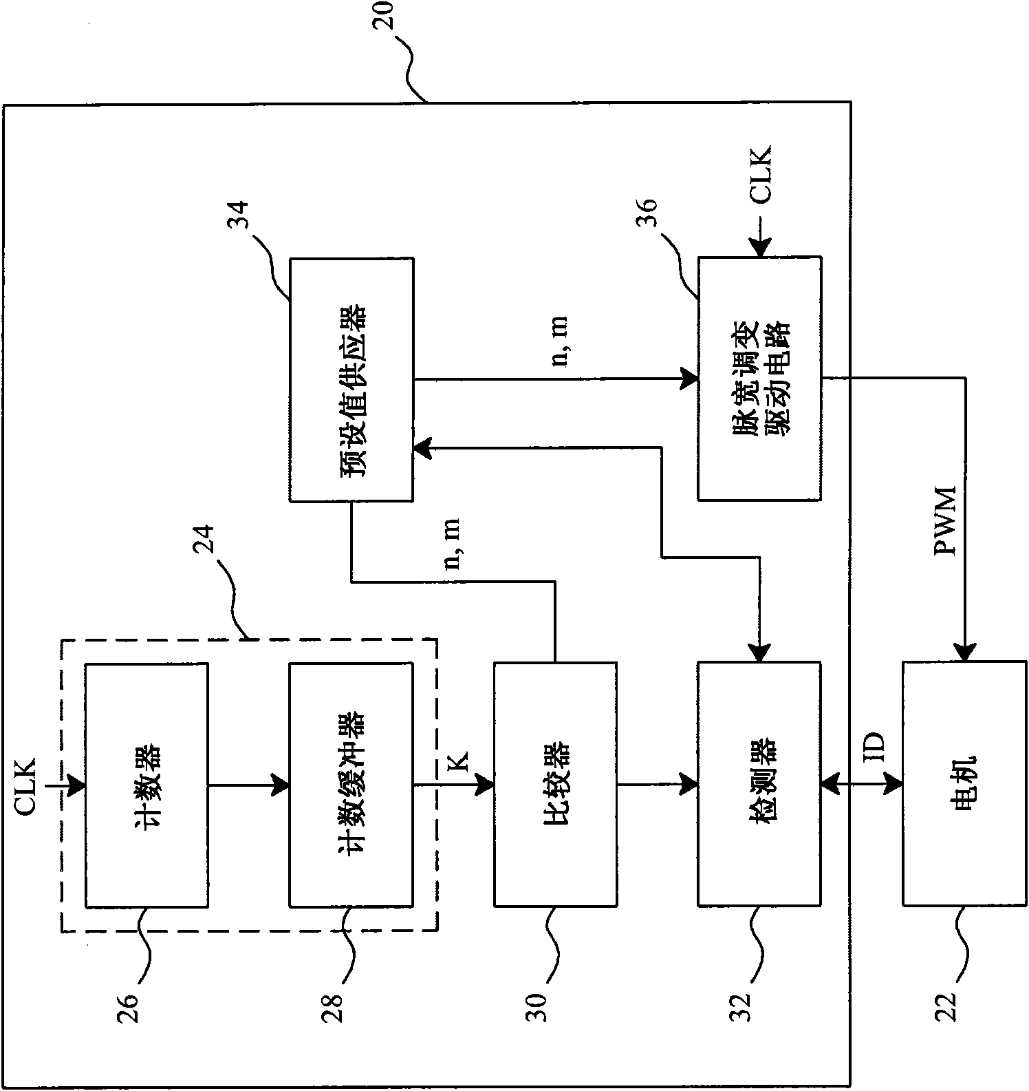
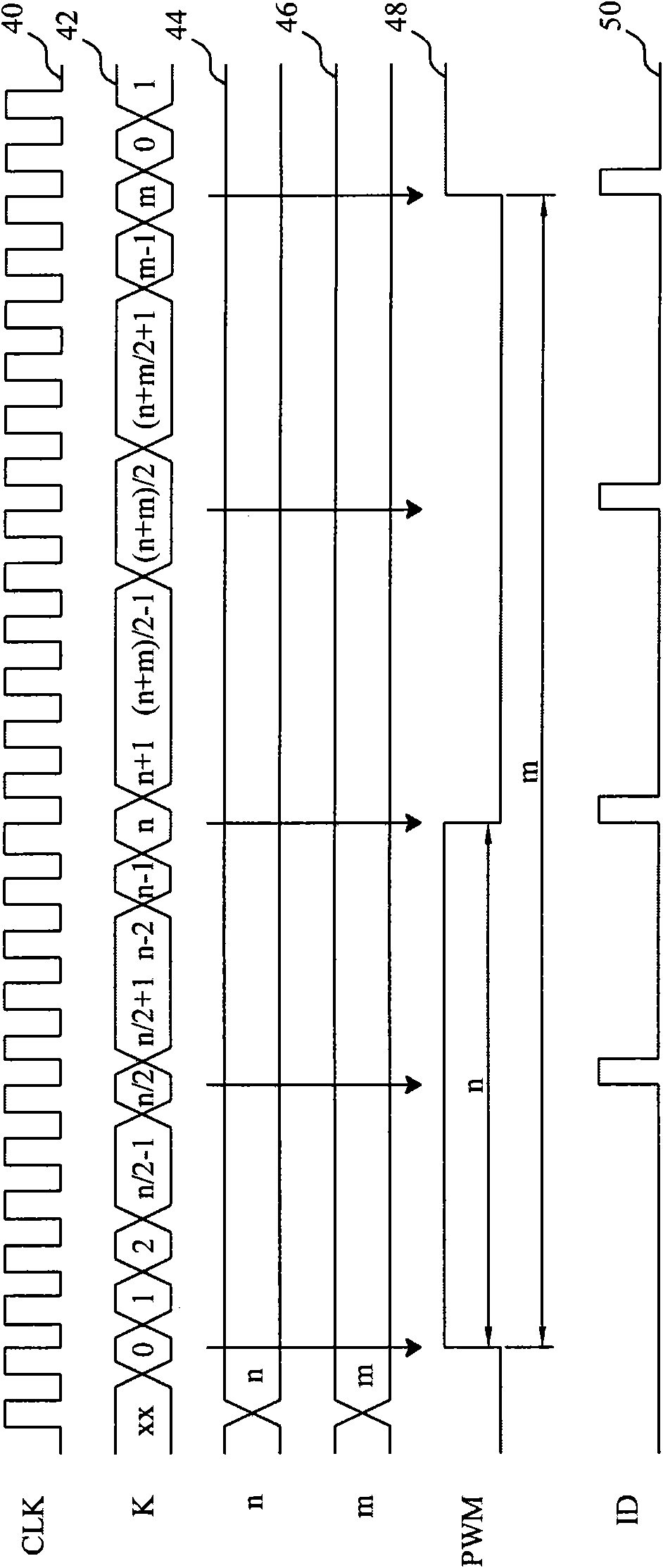
[0030] figure 2 is an embodiment of the present invention. image 3 yes figure 2 Waveform diagram of the medium signal. In the driving device 20, the preset value supplier 34 provides preset values ​​n and m, such as image 3 As shown in the waveforms 44 and 46, the pulse width modulation drive circuit 36 ​​generates the pulse width modulation signal PWM to drive the motor 22 according to the preset values ​​n and m and the source clock CLK, and the source clock CLK and the pulse width modulation signal PWM are respectively as follows image 3 As shown in waveforms 40 and 48, the length of the duty of the pulse width modulation signal PWM is equal to the period of n source clocks CLK, and the length of the period (period) of the pulse width modulation signal PWM is equal to m sources The period of the clock CLK, such as figure 2 As shown, the counting circuit 24 includes a counter 26 and a counting buffer 28. The counter 26 counts the source clock CLK, and takes the cyc...


PUM


Abstract

The invention provides a driving device and a method. The driving device comprises a pulse width modulation drive circuit, a detector, a counting circuit and a comparator, wherein the pulse width modulation drive circuit generates a pulse width modulation signal according to a preset value to drive a driven device; the detector is used for detecting the status of the driven device; when the status of the driven device is abnormal, the preset value is regulated; the counting circuit is used for counting a counting value generated by a clock; the comparator is used for comparing the counting value and a target value changed along with the preset value; and when the counting value reaches the target value, the detector is triggered. Because the driving device is combined with a detecting function and is in active detection, the reaction can be more quickly carried out, and the design cost and the time also can be reduced, thereby the work efficiency is increased.

Description

technical field [0001] The present invention relates to a driving circuit and a method, in particular to a driving circuit and a method combined with a detection function. Background technique [0002] figure 1 Shows a conventional motor control circuit. The traditional pulse width modulation drive device 10 unidirectionally gives the pulse width modulation signal PWM to control the speed of the motor 12, but the motor 12 does not return any information to the drive device 10. Generally speaking, the higher the speed of the motor 12 , the greater the current on it, but abnormalities may occur in some cases, for example, when an electric locomotive is traveling on an uphill slope, the speed of the motor 12 will be affected at this time, so when the motorcyclist wants to speed up the speed of the motor 12 to speed up When the vehicle speed is high, there may be an abnormal situation that the motor 12 rotates at a constant speed but the current on the motor 12 increases. In o...

Claims


Application Information

Patent Timeline
Patent Type & Authority Applications(China)
IPC IPC(8): H02P29/00
CPCY02P80/10
Inventor 王庆忠
Owner ELAN MICROELECTRONICS CORPORATION
Why Eureka
Try Eureka