
Method and device for switching cell

A cell handover, source cell technology, applied in electrical components, wireless communication and other directions, can solve problems such as resource waste, and achieve the effect of preventing resource waste

Active Publication Date: 2009-12-23
DATANG MOBILE COMM EQUIP CO LTD
View PDF0 Cites 21 Cited by
  • Summary
  • Abstract
  • Description
  • Claims
  • Application Information

AI Technical Summary

Problems solved by technology

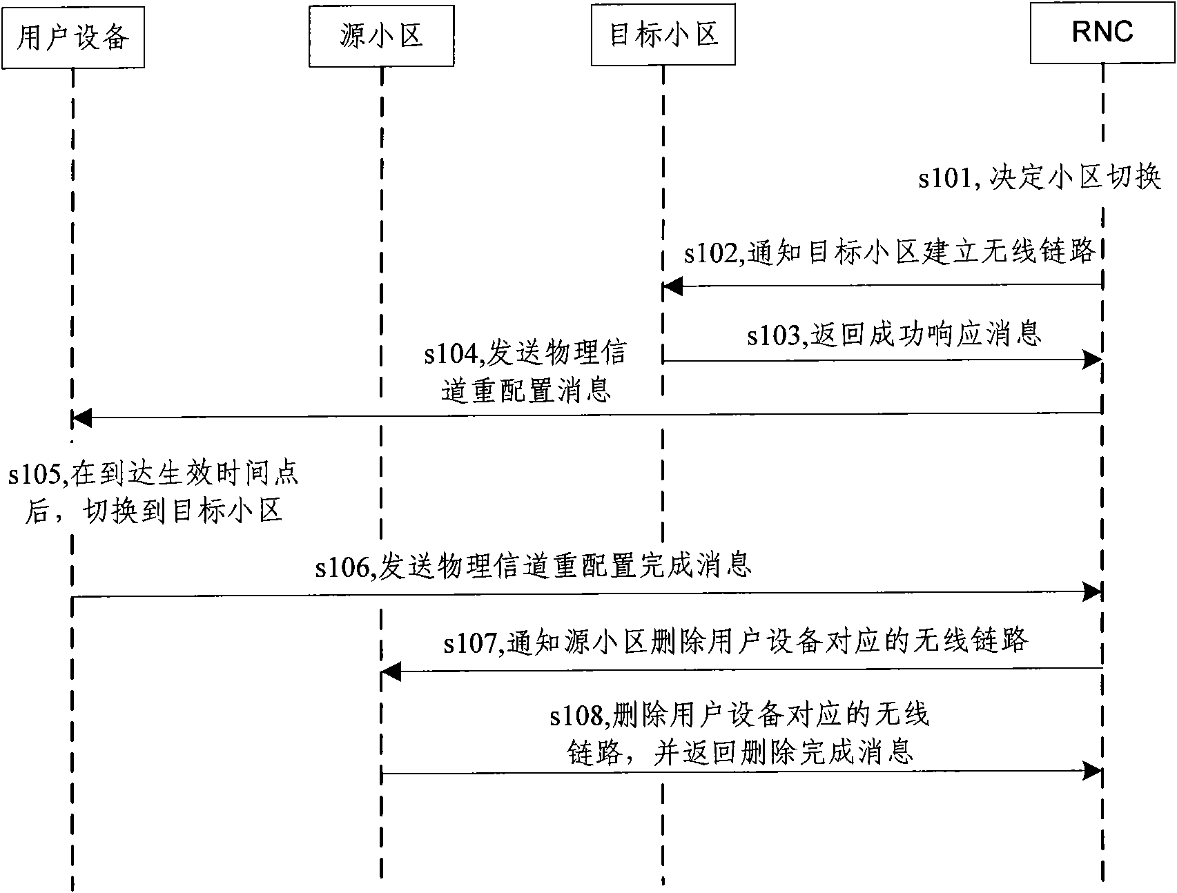
[0013] The problem to be solved by the embodiments of the present invention is to provide a method and device for cell handover, so as to overcome the problem that the source HSUPA, HSPA or HSPA+ cell will uplink Resources are allocated to users who have switched to the target cell, resulting in waste of resources

Method used


Image

  • Method and device for switching cell
  • Method and device for switching cell
  • Method and device for switching cell

Examples


Embodiment Construction

[0039] The specific implementation manners of the present invention will be further described in detail below in conjunction with the accompanying drawings and embodiments. The following examples are used to illustrate the present invention, but are not intended to limit the scope of the present invention.

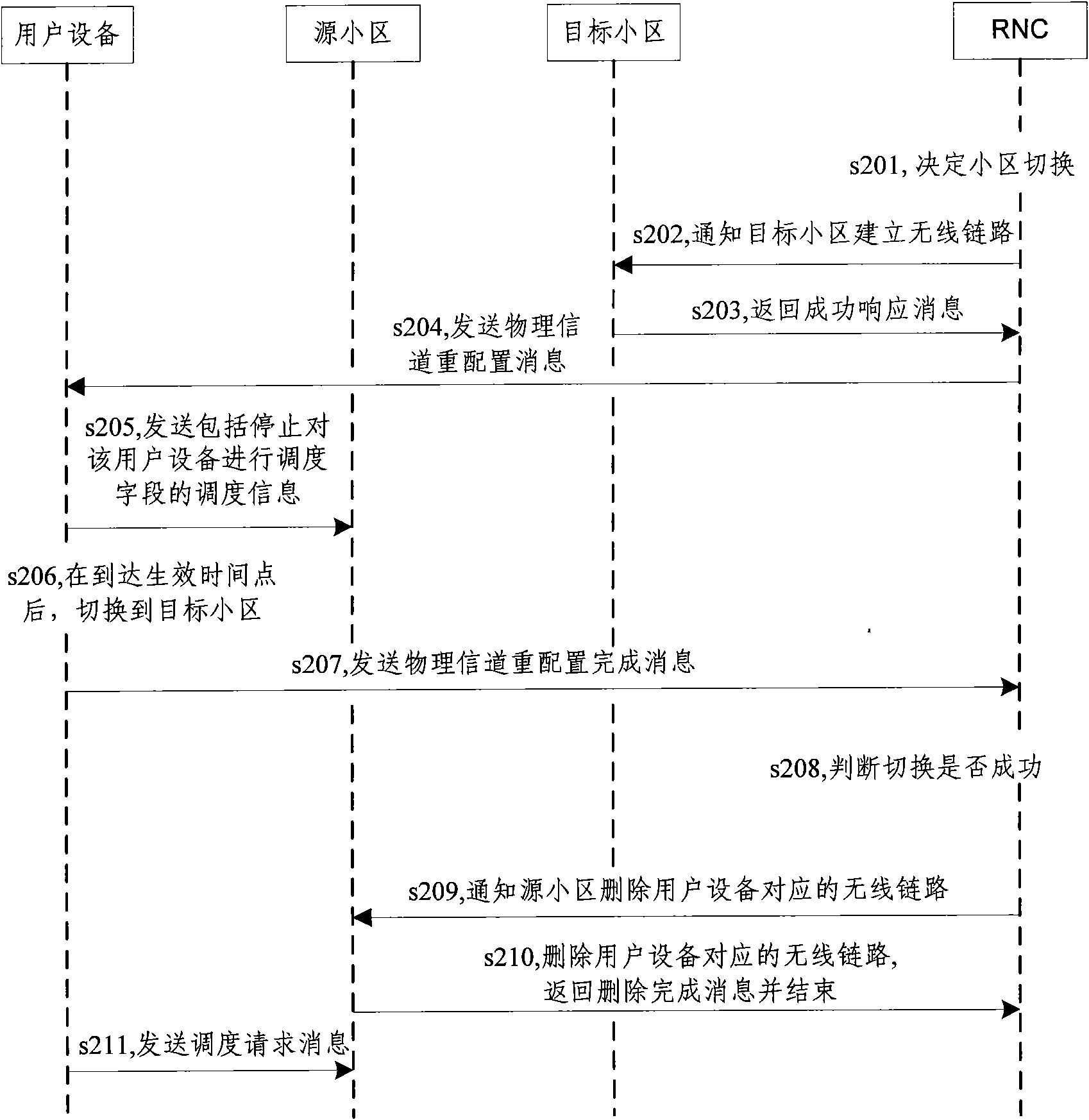
[0040] A cell handover method according to an embodiment of the present invention is as follows: figure 2 As shown, when the UE switches from the HSUPA cell to the target cell, the UE notifies the source HSUPA cell to stop scheduling the UE, refer to figure 2 , this embodiment includes the following steps:

[0041] In step s201, the RNC decides to notify the UE to perform handover from the source cell to the target cell according to the UE's measurement report.

[0042] In step s202, the RNC notifies the target cell to establish a radio link. That is, the RNC notifies the base station where the target cell is located through the Iub port NBAP signaling, and establishe...


PUM


Abstract

The invention discloses a method for switching a cell. The method comprises the following steps of: establishing a wireless chain circuit corresponding to a target cell and user equipment to be switched; transmitting a switch command to the user equipment, and designating an effective time point; notifying a source cell to stop scheduling the user equipment; at the effective time point, switchingthe user equipment to the target cell; and judging whether the switch is successful, and if so, deleting the wireless chain circuit corresponding to the source cell and the user equipment. The invention also discloses user equipment, a wireless network controller and a base station which all have the scheduling control function. When the user equipment is switched from an HSUPA, HSPA or HSPA+ cell to other cells, a source HSUPA, HSPA or HSPA+ cell is notified to stop scheduling the user equipment, so that the uplink resources of the HSUPA are effectively utilized, and the resource waste is avoided.

Description

technical field [0001] The present invention relates to the technical field of wireless communication, in particular to a cell switching method and device. Background technique [0002] HSUPA (High Speed ​​Uplink Packet Access, High Speed ​​Uplink Packet Access) technology is introduced in the Rel7 protocol version of 3GPP (3rd Generation Partnership Project, Third Generation Partnership Project), UE (User Equipment, user equipment) uplink data The transmission situation is determined according to NodeB (base station) scheduling. When the UE sends data, it needs to initiate a scheduling request to NodeB through E-RUCCH (E-DCH (Enhanced Dedicated Channel, Enhanced Dedicated Channel) Random Access Uplink Control Channel, uplink enhanced random access channel). AGCH (E-DCH Absolute Grant Channel, Enhanced Uplink Absolute Access Allowed Channel) notifies the UE of the allocated resources, and according to the timing relationship, the UE sends uplink services on the correspondin...

Claims


Application Information

Patent Timeline
Patent Type & Authority Applications(China)
IPC IPC(8): H04W36/08
Inventor 许芳丽李晓卡
Owner DATANG MOBILE COMM EQUIP CO LTD
Learn More