Electronic board and cold plate for said board

A technology of electronic circuit board and cooling plate, which is applied in the direction of circuit, cooling/ventilation/heating transformation, electrical components, etc., can solve the problems of complex manufacturing and processing of inserts, and achieve the effect of improving cooling efficiency and reducing cooling differences

Inactive Publication Date: 2011-03-23
SAMES SA MEYLAN FR
View PDF0 Cites 0 Cited by
  • Summary
  • Abstract
  • Description
  • Claims
  • Application Information

AI Technical Summary

Problems solved by technology

[0009] The manufacture and especially machining of such inserts is complex

Method used


Image

  • Electronic board and cold plate for said board
  • Electronic board and cold plate for said board
  • Electronic board and cold plate for said board

Examples


Embodiment Construction

[0038] In the following description, features and functions well known to those skilled in the art will not be described in detail.

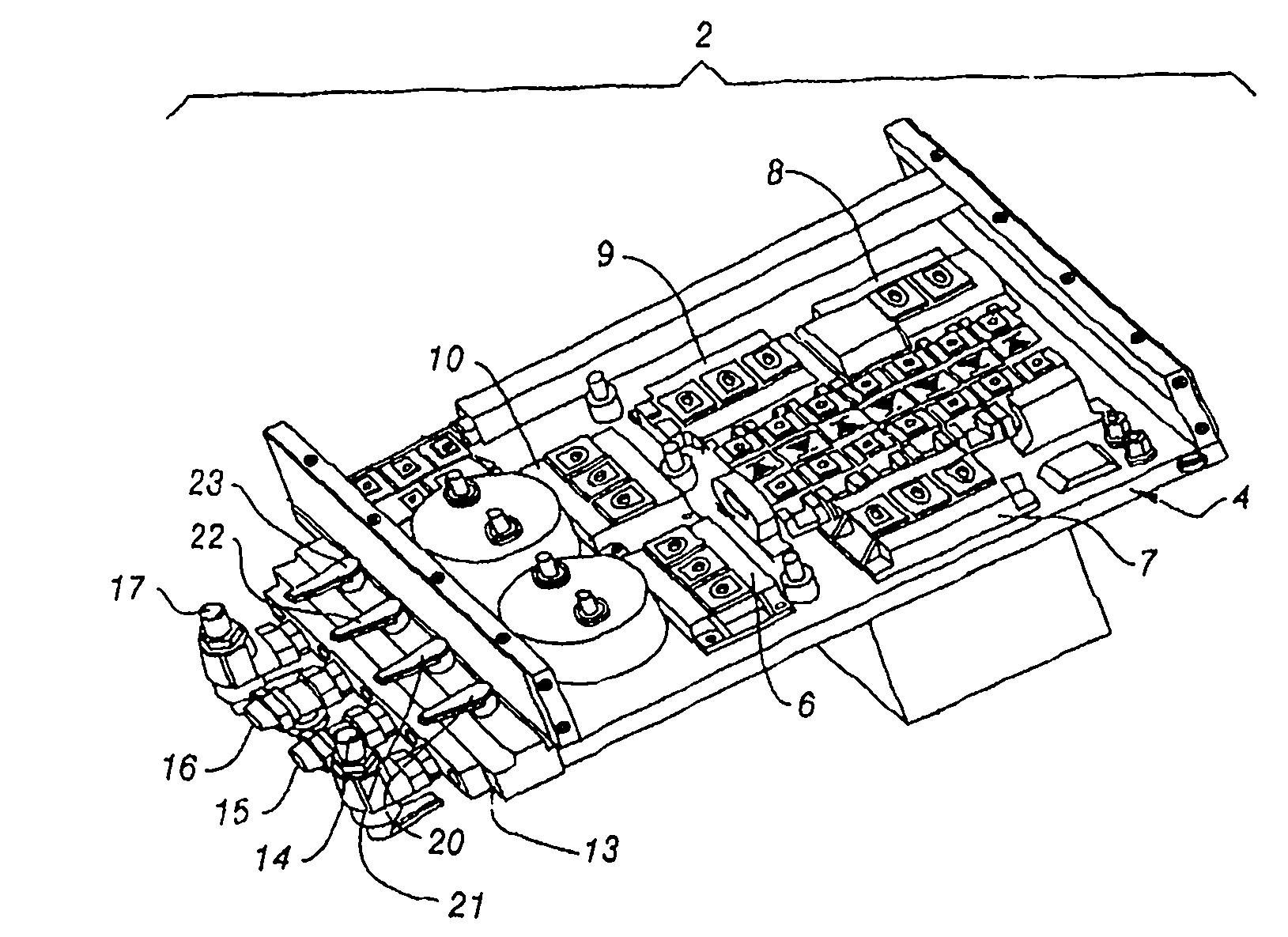
[0039] figure 1 An electronic circuit board 2 is shown with a plurality of electronic power components mounted on a cooling plate 4 .

[0040] Here, the electronic power element refers to an element that can pass an alternating current or direct current of tens of amperes without being damaged. Typically it involves a switch capable of switching this current.

[0041] Here, the circuit board 2 has five power switches 6 to 10 . These power switches are implemented with IGBT transistors (Insulated Gate Bipolar Transistors). figure 1 The other electronic components shown are not necessary to understand the operation of the cold plate and therefore will not be described in detail here.

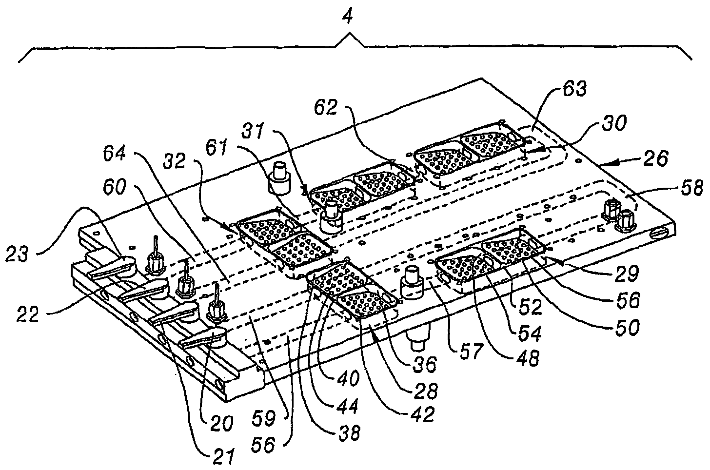
[0042] One side of the cooling plate 4 has a positioning plane 13 which removably receives four connections 14 to 17 for fluidly connecting the cooling plate 4 ...


PUM


Abstract

The board has a cold plate including a projection plate (42) between intake and evacuation holes (70, 72). Rectilinear nozzles (86-90) traverse the plate through and through by following a projection direction. Length of each nozzle along the direction is higher than / equal to width of the nozzle perpendicular to the direction for forming coolant e.g. water, jets (100-104) along the projection direction. The projection direction of each nozzle forms an angle (alpha) with respect to a direction perpendicular to a base plate (78), where the angle ranges between minus 30 to plus 30 degrees.

Description

technical field [0001] The invention relates to an electronic circuit board and a cooling plate for cooling the circuit board. Background technique [0002] There is an electronic circuit board which has: [0003] - at least one electronic power component with a base plate in direct contact with the heat-carrying fluid, [0004] - a cooling plate on which the base plate of the electronic power components is fastened in a heat-tight manner against the heat transfer fluid, the cooling plate having: [0005] at least one recess opening to the underside of the base plate of the electronic power component, [0006] an inlet hole for the heat transfer fluid to enter the recessed portion, and [0007] • A discharge hole through which the heat transfer fluid flows out of the recessed portion. [0008] For these electronic circuit boards, some plastic inserts are inserted into the recessed parts. Each insert has a plurality of channels that are fluidly connected to the access ho...

Claims


Application Information

Patent Timeline
Patent Type & Authority Patents(China)
IPC IPC(8): H01L23/473H05K7/20H05K7/14
CPCH01L23/4735H05K7/20345H05K7/20927H01L2924/0002H01L2924/00
Inventor C·托姆S·罗伯特
Owner SAMES SA MEYLAN FR
Why Eureka
Try Eureka