Keeper joint, keeper unit, scribing head and scribing device

A holder and scribing head technology, which is applied to glass cutting devices, manufacturing tools, glass manufacturing equipment, etc., can solve the problems of low position accuracy, difficulty in dismounting, and difficulty in removing the holder, and achieve the effect of improving precision

Inactive Publication Date: 2009-12-30
MITSUBOSHI DIAMOND IND CO LTD
View PDF1 Cites 16 Cited by
  • Summary
  • Abstract
  • Description
  • Claims
  • Application Information

AI Technical Summary

Problems solved by technology

Therefore, once a curved scribing line is formed, there is a disadvantage that the positional accuracy of the scribing line will decrease even in the case of a straight line.
Again, since the holder is pressed into the opening 123 of the holder connector 120, it is difficult to remove it.
In particular, when the holder is exchanged using an automatic tool changer such as a robot arm, there is a disadvantage that it becomes difficult to remove the holder

Method used


Image

  • Keeper joint, keeper unit, scribing head and scribing device
  • Keeper joint, keeper unit, scribing head and scribing device
  • Keeper joint, keeper unit, scribing head and scribing device

Examples


Embodiment Construction

[0041] The above and other technical features and advantages of the present invention will be described in more detail below in conjunction with the accompanying drawings.

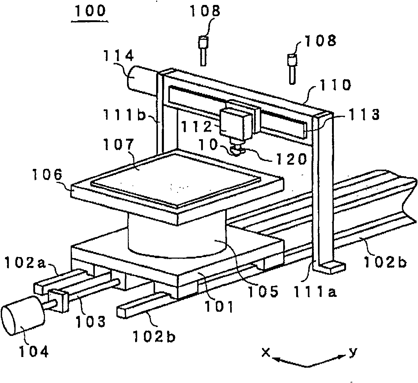
[0042] Figure 8 It is a perspective view showing a scribing device using a scribing head according to an embodiment of the present invention. In this scribing device, the same symbols are given to the same parts as those in the above-mentioned conventional example. In the scribing device 1 of the present embodiment, the moving table 101 is held movably in the y-axis direction along a pair of guide rails 102a and 102b. The ball screw 103 is screwed with the moving table 101 . The ball screw 103 is driven and rotated by the motor 104 to move the moving table 101 in the y-axis direction along the guide rails 102a and 102b. A motor 105 is provided on the upper surface of the mobile stand 101 . The motor 105 rotates the platform 106 on the xy plane to be positioned at a predetermined angle. The brittle ma...


PUM


Abstract

The invention provides a keeper joint, a keeper unit, a scribing head and a scribing device; the keeper having a scribing wheel is appropriately located at the keeper joint, and the keeper is easily detached. A communicating pore is arranged at the side of the opening of the keeper joint; the communicating pore keeps the pin to rotate in the specific angle range. The pin is provided with a first plane portion parallel to a shaft and a second plane portion different from the angle. The keeper is inserted into the opening so that the inclined portion contacts the plane portion to compose the keeper unit. And the keeper is appropriately located, and the keeper unit and scribing head are freely detached.

Description

technical field [0001] The invention relates to a scribing device for forming a scribing line on a brittle material substrate, a scribing head, a holder unit, and a holder joint. Background technique [0002] Conventionally, in flat-panel displays such as liquid crystal display panels and liquid crystal projector substrates, mother glass substrates are bonded in the manufacturing process and then cut into individual panels of a specific size. Here, the breaking of a brittle material substrate such as a mother glass substrate includes a scribing step and a breaking step, and a scribing device is used in the scribing step. [0003] figure 1 It is a perspective view showing the scribing device disclosed in Patent Document 1. FIG. In this scribing device 100 , the moving table 101 is held movably in the y-axis direction along a pair of guide rails 102 a and 102 b. The ball screw 103 is screwed with the moving table 101 . The ball screw 103 is driven and rotated by the motor ...

Claims


Application Information

Patent Timeline
Patent Type & Authority Applications(China)
IPC IPC(8): C03B33/027
CPCC03B33/027C03B33/03C03B33/033C03B33/037C03B33/10Y02P40/57
Inventor 山本正男
Owner MITSUBOSHI DIAMOND IND CO LTD
Why Eureka
Try Eureka