
Separated cover structure of motorbike clutch

A clutch and separation cover technology, applied in the direction of clutches, mechanical drive clutches, mechanical equipment, etc., can solve the problems of reduced crankshaft running stability, increased engine vibration, cumbersome operation, etc., achieves convenient maintenance and replacement, and reduces maintenance costs , the effect of simple operation

Inactive Publication Date: 2011-04-13
力帆科技(集团)股份有限公司
View PDF0 Cites 0 Cited by
  • Summary
  • Abstract
  • Description
  • Claims
  • Application Information

AI Technical Summary

Problems solved by technology

[0002] The clutch separation mechanism is composed of a joystick and a push rod. Both the joystick and the push rod are installed on the engine crankcase cover and form a whole with the crankcase cover. This has a serious use defect: when the engine clutch needs to be repaired or replaced , the entire engine crankcase cover must be disassembled. Not only is the operation cumbersome, time-consuming and laborious, but also frequent disassembly and assembly will easily damage the sealing performance of the crankcase and the dynamic balance of the crankshaft. On the one hand, the crankcase cover gasket must be replaced every time it is disassembled. , the cost is extremely high; on the other hand, it will reduce the stability of the crankshaft and increase the vibration of the engine

Method used


Image

  • Separated cover structure of motorbike clutch
  • Separated cover structure of motorbike clutch
  • Separated cover structure of motorbike clutch

Examples


Embodiment Construction

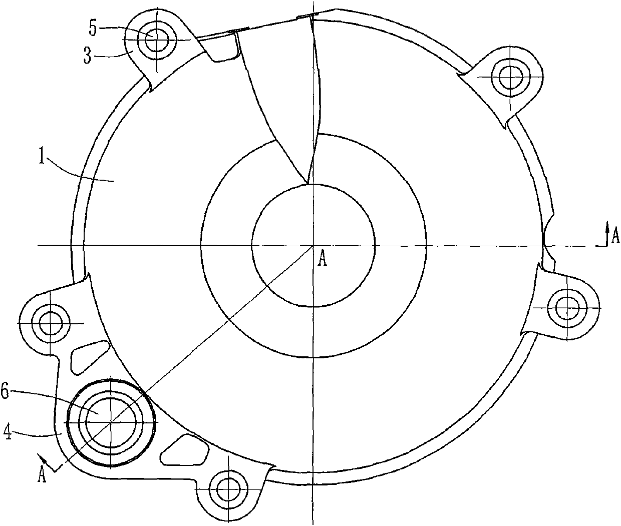
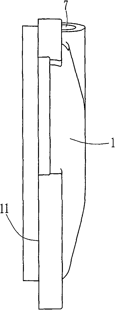
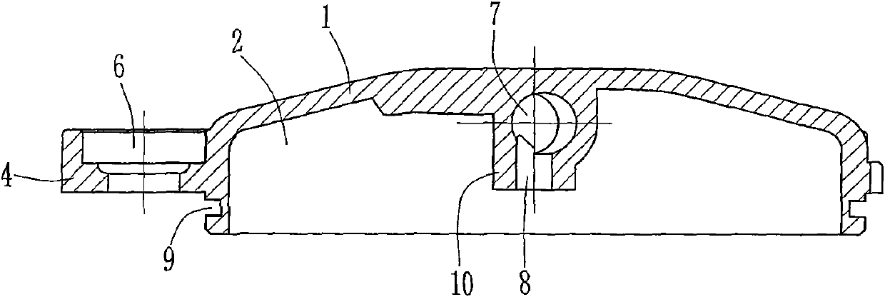
[0015] Below in conjunction with accompanying drawing and embodiment, the present invention will be further described:

[0016] like figure 1 , figure 2 , image 3 As shown, a motorcycle clutch release cover structure has a cover body 1 with an inner cavity 2, the cover body 1 is circular, the front end of the cover body 1 is open, the rear end is closed, and the outer circumference of the cover body 1 is In the stage where the front is small and the back is large, the transition surface 11 between the large stage and the small stage is the installation surface. A ring groove 9 is opened on the small diameter section of the outer circumference of the cover body 1 for the installation of the O-ring. A plurality of lugs 3 are integrally formed on the large-diameter section of the outer circumference of the cover body 1, and each lug 3 is provided with a mounting hole 5; a mounting seat 4 is integrally formed at the lower left part of the outer circumference of the large-diam...


PUM


Abstract

The invention discloses a separated cover structure of a motorbike clutch, which comprises a cover body (1) with an inner chamber (2), wherein the front end of the cover body (1) is open and the back end is closed; the periphery side of the cover body (1) is provided with a support lug (3) and an installing seat (4), wherein the support lug (3) is opened with an installing through hole (5); the installing seat (4) is opened with a starting shaft through hole (6); the closed end of the cover body (1) is provided with an operating lever hole (7) in a radial direction; the upper end of the operating lever hole (7) is penetrated to the top surface of the cover body (1) and the lower end is extended into the middle part of the closed end of the cover body (1) and communicated with the inner chamber (2) of the cover body (1) by a push rod hole (8). The separated cover structure provides convenience for the maintenance and replacement of the clutch, is simple to operate, saves time and labor, and guarantees the tightness of a crankcase and the dynamic balance of the crankcase not to be affected, thus greatly reducing the maintenance cost of the clutch.

Description

technical field [0001] The present invention relates to an engine component, in particular, to a clutch release cover on an engine. Background technique [0002] The clutch release mechanism is composed of a lever and a push rod. The lever and the push rod are installed on the crankcase cover of the engine and form a whole with the crankcase cover, so there is a serious use defect: when the engine clutch needs to be repaired or replaced , the entire engine crankcase cover must be completely disassembled, which is not only cumbersome and time-consuming, but also frequent disassembly and assembly can easily damage the sealing of the crankcase and the dynamic balance of the crankshaft. On the one hand, the crankcase cover must be replaced every time. , the cost is extremely high; on the other hand, it will reduce the smoothness of the crankshaft operation and increase the vibration of the engine. SUMMARY OF THE INVENTION [0003] The technical problem to be solved by the pre...

Claims


Application Information

Patent Timeline
Patent Type & Authority Patents(China)
IPC IPC(8): F16D23/12
Inventor 李力唐勇
Owner 力帆科技(集团)股份有限公司
Learn More