
Heat pump air-conditioning system and heat recovery system

A technology of heat pump air conditioning and heat recovery, which is applied in heat recovery systems, fluid heaters, refrigeration and liquefaction, and can solve problems such as limiting the scope of use of water-cooled heat pumps

Inactive Publication Date: 2009-12-30
鑫鲁禹能源科技(北京)有限公司
View PDF0 Cites 21 Cited by
  • Summary
  • Abstract
  • Description
  • Claims
  • Application Information

AI Technical Summary

Problems solved by technology

[0008] During cooling in summer, although the indoor heat energy can be converted into sanitary hot water through the condenser, the system must be equipped with a cooling tower (the water source heat pump must have a water extraction well and a recharge well) to ensure the stability of the system during the cooling process, thereby Limits the scope of use of water-cooled heat pumps (or water-source heat pumps)

Method used


Image

  • Heat pump air-conditioning system and heat recovery system
  • Heat pump air-conditioning system and heat recovery system
  • Heat pump air-conditioning system and heat recovery system

Examples


Embodiment 1

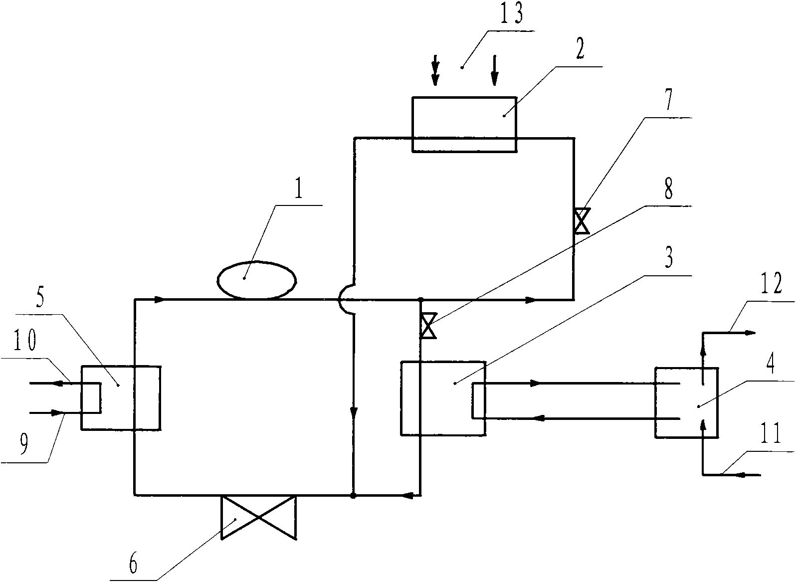
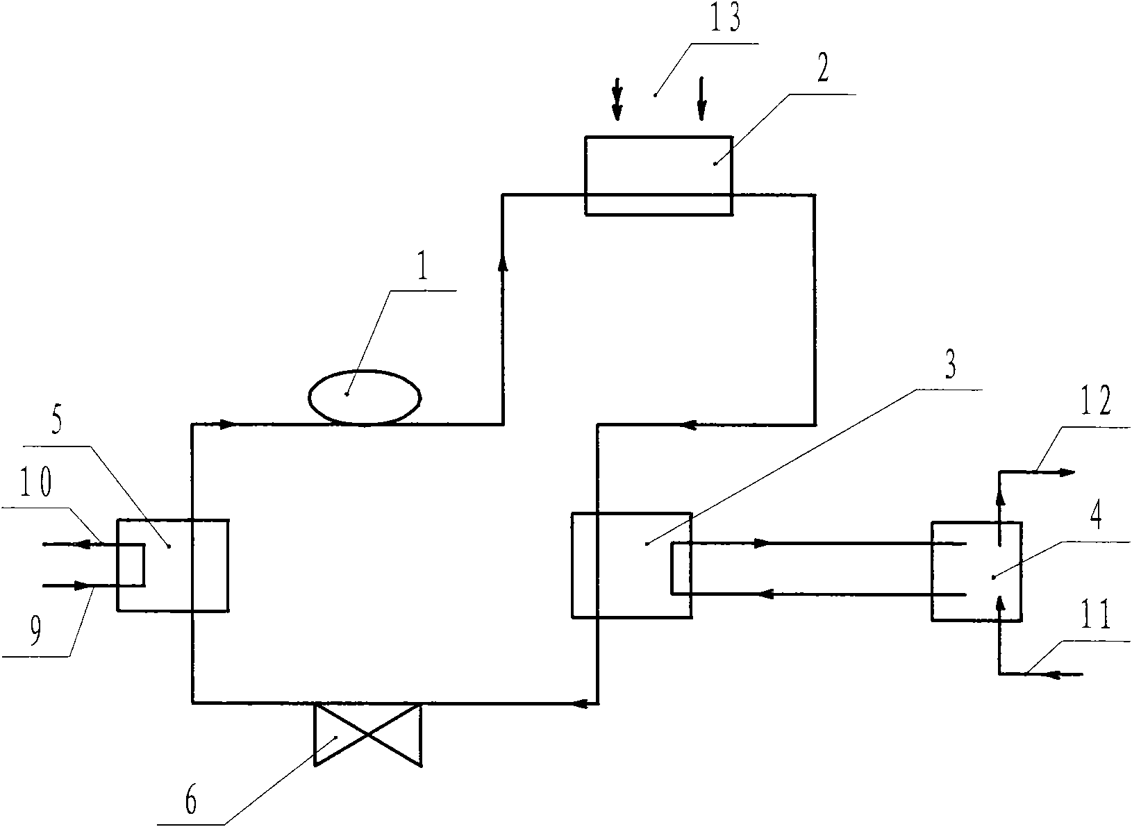
[0027] A heat pump air conditioning system and heat recovery system, including a compressor 1, an evaporator 5, a condenser 2, and an expansion valve 6; the heat release end of the heat pump is composed of two condensers, one of which is an air heat exchanger 2, Its second is water heat exchanger 3, and described water heat exchanger 3 is connected with water tank 4 (or water source) by pipeline, and water tank 4 is provided with water inlet 11 and water outlet 12; Air heat exchanger 2 and water heat exchanger 3 is connected in parallel with the pipeline to form a circuit with the compressor 1, the evaporator 5, and the expansion valve 6. The pipeline is equipped with a control valve 7 and a control valve 8; the water tank 4 is heat-preserved; Heater, air heat exchanger 2 adopts metal fin fan coil structure, and is designed according to the design standard of ultra-low temperature air source heat pump.

[0028] Summer work process:

[0029] The unit automatically enters the h...

Embodiment 2

[0033] The air heat exchanger 2 and the water heat exchanger 3 are connected in series without using the control valve 7 and the control valve 8 . When working in summer, the air heat exchanger 2 and water heat exchanger 3 exchange the heat released by the system to the air and water in the water tank respectively; when working in winter, the air heat exchanger 2 and water heat exchanger 3 can work simultaneously , can also use one of them to work.

Embodiment 3

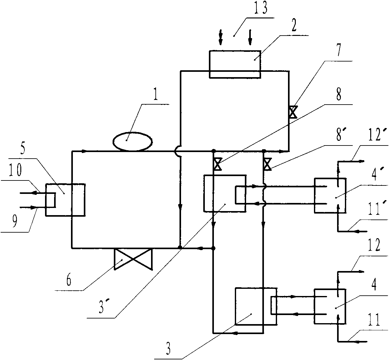
[0035] The water heat exchanger 3 and the water heat exchanger 3' are connected in parallel and then connected in parallel with an air heat exchanger 2. The water heat exchanger 3 and the water heat exchanger 3' are respectively controlled by the control valve 8 and the control valve 8'. This system is suitable for two situations that have different requirements for hot water temperature in summer, such as bathrooms and swimming pools.


PUM


Abstract

The invention discloses a heat pump air-conditioning system and heat recovery system, belonging to a combined heat pump technology of heating and refrigeration. The system comprises a compressor, an evaporator, condensers and an expansion valve, and is characterized in that at least two condensers, i.e. heat exchangers, are arranged at one end of a heat pump, wherein one of the condensers is an air heat exchanger, and the other one is a water heat exchanger. The water heat exchanger is connected with a water tank (or a water source) through a pipeline, and a water inlet and a water outlet are arranged on the water tank. The invention provides a heat pump air-conditioning technology, which fully and efficiently utilizes the air energy and prepares hot water while refrigerating, aiming to overcome the technical defect that the heat exhausted by the heat pump outdoors in summer is not efficiently utilized in the prior art. The invention is mainly used for places needing both the indoor refrigeration and the hot water in the summer, and can be used as both an air source heat pump and a water source heat pump according to the objective environment in which a machine set is located in winter.

Description

technical field [0001] The invention relates to a heat pump air conditioning system and a heat recovery system, belonging to the combined heat pump technology of heating and cooling. Background technique [0002] Both the air-cooled heat pump air-conditioning system and the water-cooled heat pump air-conditioning system are based on the reverse Carnot cycle principle. The heat-absorbing working medium absorbs heat energy from a low-temperature heat source and releases heat from a high-temperature heat source. Through continuous heat absorption and heat release cycles, refrigeration and heating are achieved. Purpose. [0003] At present, commonly used air conditioners are generally composed of a compressor, a condenser, an evaporator, and an expansion valve. When the air-cooled heat pump (air source heat pump) is cooling in summer, the heat energy absorbed by the heat-absorbing working medium in the evaporator reduces the water temperature, thereby achieving the purpose of c...

Claims


Application Information

Patent Timeline
IPC IPC(8): F25B6/00F25B6/02F25B49/02F25B6/04F24H4/04F25B39/04
CPCY02B30/52Y02B30/123Y02B30/12Y02B30/13
Inventor 王言明
Owner 鑫鲁禹能源科技(北京)有限公司
Learn More