Colored optical filter and manufacturing method thereof

The technology of a color filter and a manufacturing method, which is applied in the field of color filters, can solve the problems of many factors of uneven thickness of the color filter and high manufacturing cost of the color filter, and achieve the reduction of the factors of uneven thickness and structural layers. The effect of reducing the quantity and reducing the manufacturing cost

Inactive Publication Date: 2009-12-30
SHENZHEN LAIBAO HI TECH
View PDF0 Cites 2 Cited by
  • Summary
  • Abstract
  • Description
  • Claims
  • Application Information

AI Technical Summary

Problems solved by technology

[0006] One of the technical problems to be solved by the present invention is to provide a color filter, which overcomes the defects of high manufacturing cost of the color filter and many factors affecting the thickness of the color filter in the prior art
[0007] The second technical problem to be solved by the present invention is to provide a method for manufacturing a color filter to realize the manufacture of the above-mentioned color filter, and to overcome the high manufacturing cost of the color filter caused by the prior art and the influence on the thickness of the color filter. Defects with many uneven factors

Method used


Image

  • Colored optical filter and manufacturing method thereof
  • Colored optical filter and manufacturing method thereof
  • Colored optical filter and manufacturing method thereof

Examples


Embodiment 1

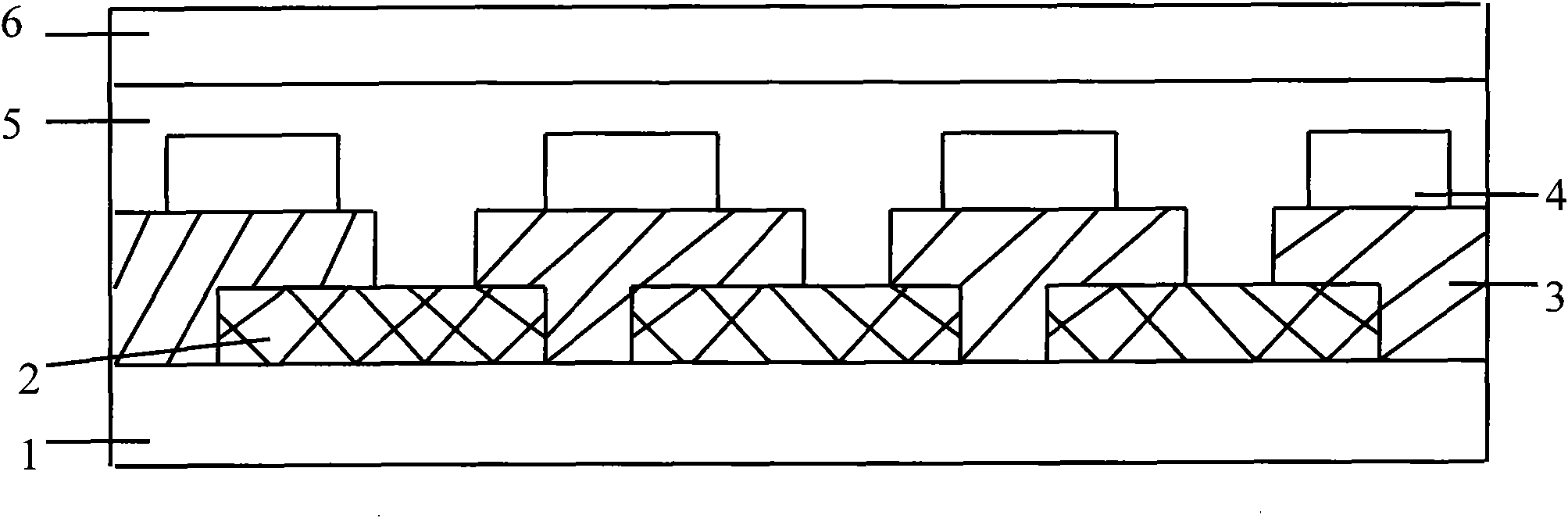
[0030] Such as figure 2 As shown, the color filter of the present invention includes a substrate 1, a color filter layer 3, a reflective film layer 4, an insulating protective layer 5 and a transparent electrode layer 6. The color filter layer 3 includes adjacently arranged red (R) and green ( G) and blue (B) sub-pixels are arranged in the order of R, G, B (or R, B, G order, or B, G, R order, etc.), and the reflective film layer 4 is a matrix grid-like metal film Or a metal alloy film (the matrix grid structure means that the reflective film layer 4 is provided with a metal film or a metal alloy film on the grid of the matrix grid structure, leaving blanks in the grid for light transmission). The color film layer 3, the reflective film layer 4, the insulating protective layer 5 and the transparent electrode layer 6 are sequentially laminated and covered on the substrate 1 from the inside to the outside in the order of the color film layer 3, the reflective film layer 4, the insul...

Embodiment 2

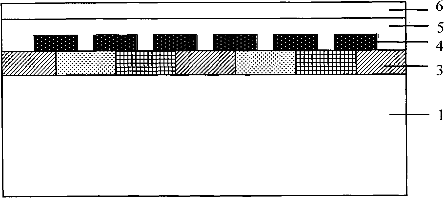
[0036] Such as image 3 As shown, this embodiment is basically the same as the first embodiment, and the difference lies in:

[0037] A reflective film layer 4, a first insulating protective layer 5, and a transparent electrode layer 6 are provided on one side of the substrate 1, and the reflective film layer 4, the first insulating protective layer 5 and the transparent electrode layer 6 are stacked in order from the inside to the outside. A color film layer 3 and a second insulating protective layer 7 are arranged on the other side of the substrate 1, and the color film layer 3 and the second insulating protective layer 7 are sequentially stacked from the inside to the outside.

Embodiment 3

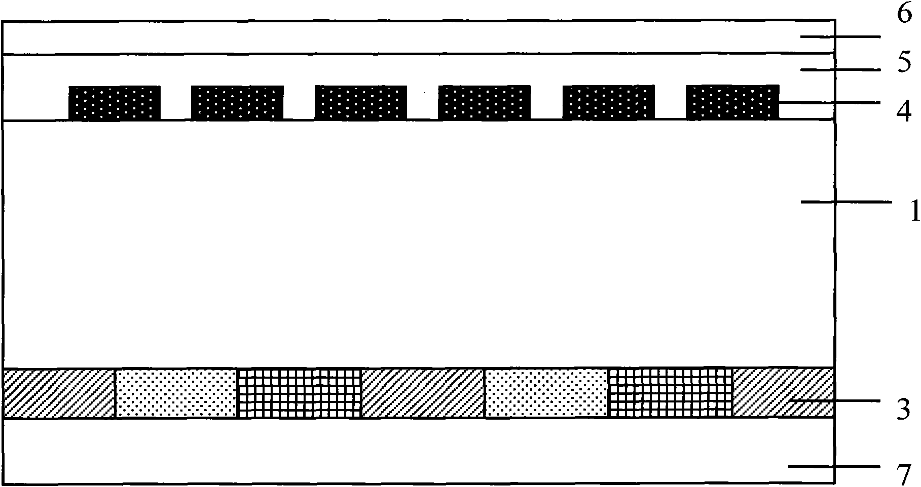
[0039] Such as Figure 4 As shown, this embodiment is basically the same as the first embodiment, and the difference lies in:

[0040] The color film layer 3, the first insulating protection layer 5 and the transparent electrode layer 6 are arranged on one side of the substrate 1, and the color film layer 3, the first insulating protection layer 5 and the transparent electrode layer 6 are stacked in order from the inside to the outside. A reflective film layer 4 and a second insulating protective layer 7 are arranged on the other side of the substrate 1, and the reflective film layer 4 and the second insulating protective layer 7 are sequentially stacked from the inside to the outside.


PUM


Abstract

The invention relates to a colored optical filter and a manufacturing method thereof. The colored optical filter comprises a base plate, a colored film layer which is overlapped or nested on the base plate, a reflecting film layer, an insulating protective layer and a transparent electrode layer, wherein the transparent electrode layer is positioned at the outermost layer, and the insulating protective layer is covered on the colored film layer or the reflecting film layer or simultaneously covered on the colored film layer and the reflecting film layer that are nested with each other; the colored film layer comprises red sub-pixel, green sub-pixel and blue sub-pixel which are arranged in an adjacent way; the reflecting film layer is a metal film or a metal alloy film having matrix latticed shape, and the part of the metal film or the metal alloy film of the reflecting film layer is arranged in the adjacent overlap area or adjacent gap area correspondingly to the sub-pixels that blocks out the colored film layer along the projection direction being vertical to the base plate; the manufacturing method can be used for making the colored film layer and the reflecting film layer in different steps, so that the colored optical filter can be manufactured. The invention omits a light shading layer, so that the number of the structure layer of the colored optical filter can be reduced, and the manufacturing cost of the colored optical filter is lowered; meanwhile, the factor of uneven thickness of the colored optical filter is reduced, and the thickness uniformity of the colored optical filter is improved.

Description

Technical field [0001] The invention relates to a color filter, and also to a manufacturing method of the color filter, in particular to a color filter and a manufacturing method thereof. Background technique [0002] The existing color filter structure is as figure 1 As shown, it includes a substrate 1, a light-shielding layer 2, a color film layer 3, a reflective film layer 4, an insulating protective layer 5, and a transparent conductive electrode layer 6. The light-shielding layer 2 corresponds to each of the red (R) and green layers provided on the color film layer 3. (G), blue (B) sub-pixel gaps (here brightened by light leakage) or overlap (here darkened by overlap, not shown in the figure), in order to block the bright or dark areas to ensure color The uniformity of the filter display increases the contrast of the product. [0003] The existing color filter structure has the following defects: [0004] 1. There are a large number of structural layers, and the functions o...

Claims


Application Information

Patent Timeline
Patent Type & Authority Applications(China)
IPC IPC(8): G02B5/20
Inventor 郭志勇王连彬钟荣苹李绍宗王士敏商陆平陈雄达
Owner SHENZHEN LAIBAO HI TECH
Why Eureka
Try Eureka