Backlight module and light guide plate

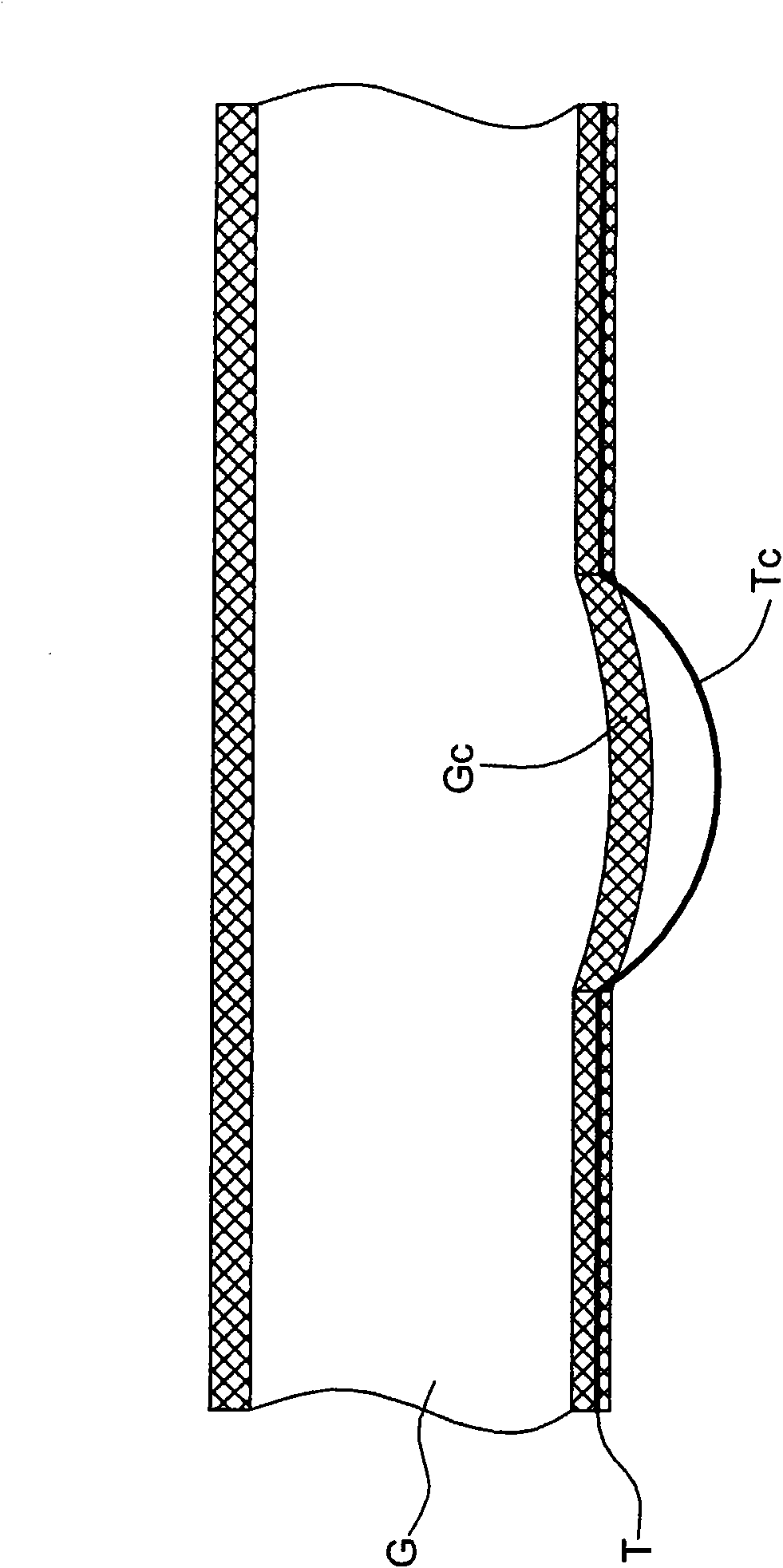
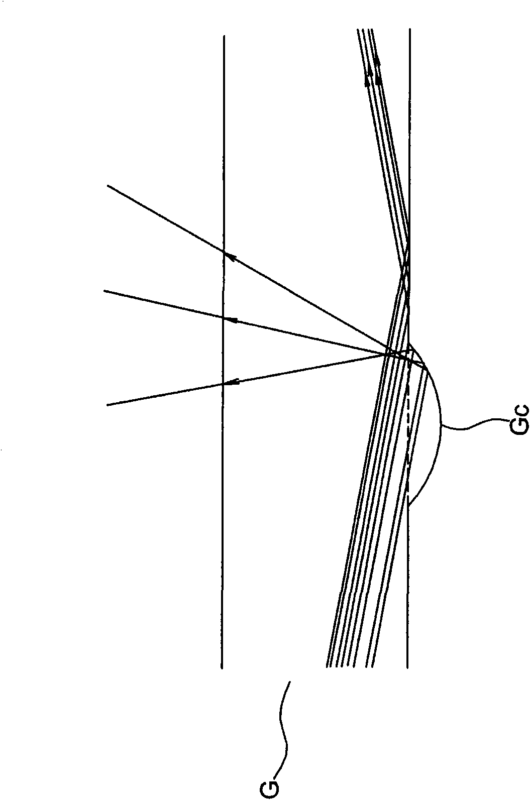
A technology of backlight module and light guide plate, applied in the direction of light guide, light guide of lighting system, optics, etc., can solve the problems of poor light diffusion efficiency, inability to obtain geometric shapes, poor surface structure Gc molding, etc., to solve uneven diffusion , Improve light diffusion efficiency, increase the effect of overall roughness

Inactive Publication Date: 2009-12-30
WINTEK CORP
View PDF0 Cites 17 Cited by
  • Summary
  • Abstract
  • Description
  • Claims
  • Application Information

AI Technical Summary

Problems solved by technology

[0004] However, in the process of injection molding, the surface structure Gc of the light guide plate is often poorly formed due to the presence of air between the concave structure Tc and the injection material, and it is impossible to obtain a geometric shape with a deep concave depth (such as a cone or spherical), such as Figure 1A shown
Therefore, if Figure 1B As shown, when the light enters the light guide plate G with poorly formed surface structure Gc from the left side of the figure, the diffusion efficiency of light will deteriorate due to the poorly formed surface structure Gc.

Method used


Image

  • Backlight module and light guide plate
  • Backlight module and light guide plate
  • Backlight module and light guide plate

Examples


Embodiment Construction

[0019] The following description will illustrate embodiments of the present invention with reference to related drawings, so that anyone skilled in the art can implement the present invention. Although there are differences in the embodiments of the present invention, the structures or features described herein are used for any implementation, without departing from the scope of the present invention, it can be implemented in other embodiments, not just the following implemented in the manner described above. In addition, the arrangement and position of the individual components in each disclosed embodiment can be modified appropriately without departing from the scope of the present invention, so the protection scope of the present invention should be defined by the appended claims.

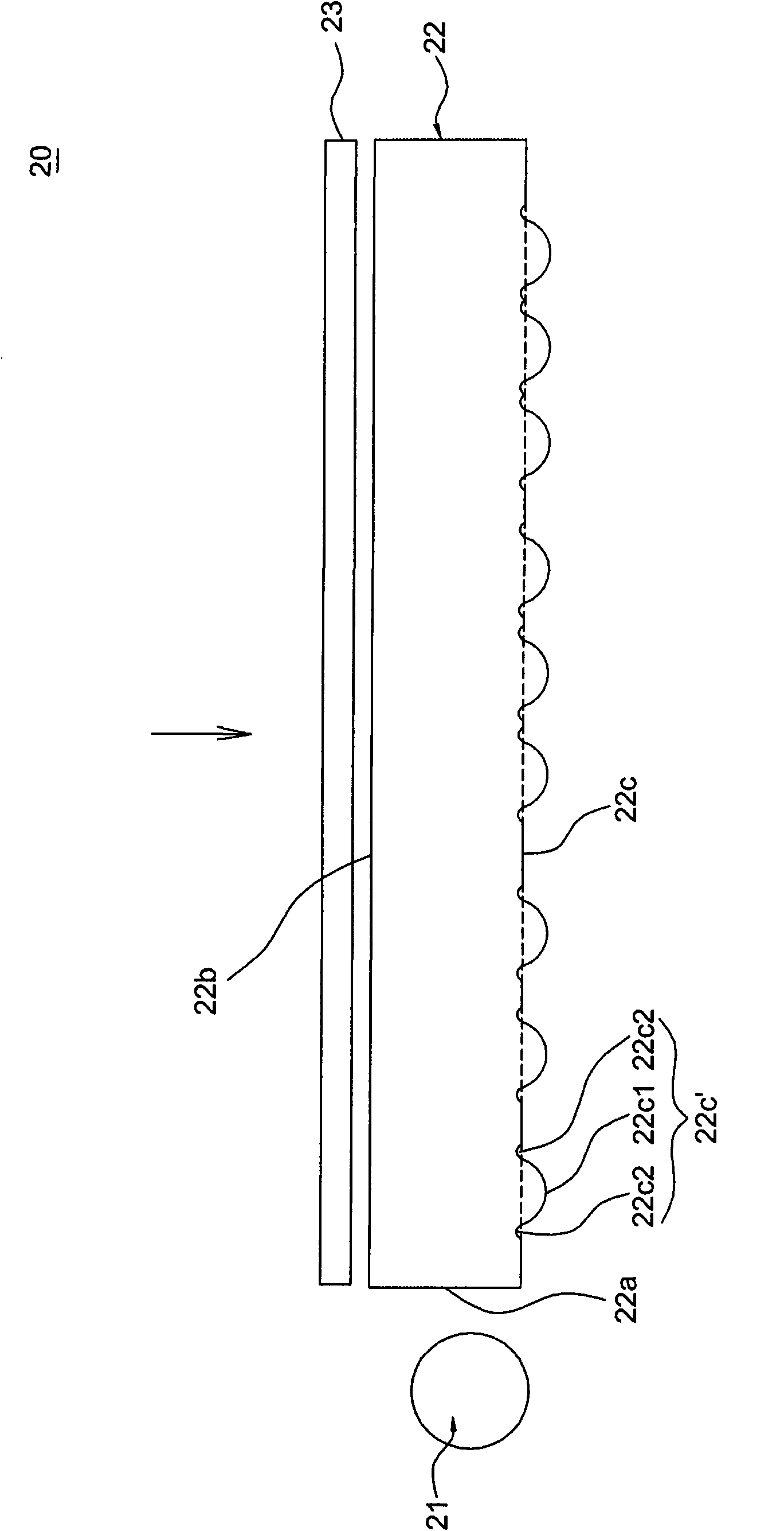
[0020] figure 2 is a schematic diagram showing a backlight module according to an embodiment of the present invention. The backlight module 20 includes a light source 21 , a light guide plate...


PUM


Abstract

The invention relates to a backlight module and a light guide plate. The light guide plate comprises a light inlet surface, a light outlet surface and a light reflecting surface. The light inlet surface receivers light rays emitted by at least one light source, and the light rays are educed by the light outlet surface. The light reflecting surface is arranged opposite to the light outlet surface and used for reflecting the light rays entering the light guide plate from the light inlet surface to the light outlet surface, wherein the light outlet surface and / or the light reflecting surface comprises at least one composite structure comprising a main structure and an auxiliary structure, and the auxiliary structure is arranged on the side edge of the main structure. The backlight module and the light guide plate increase the integral roughness of the light outlet surface and / or the light inlet surface by utilizing the combination of a convex curve surface and a concave curve surface of the composite structure so as to solve the problem of heterogeneous diffusion which probably occurs when the light rays enter the light guide plate, thereby achieving the effect of improving the light diffusion efficiency.

Description

technical field [0001] The invention relates to a light guide plate structure, especially a light guide plate structure with good light guide efficiency. Background technique [0002] Most of the current light guide plates are processed by etching, and the shapes of their surface structures include: circle, square, rhombus, etc. Various geometric shapes. [0003] Please refer to Figure 1A , generally when making the light guide plate G, the recessed structure Tc is often directly etched on the template T. Afterwards, the light guide plate G is formed on the template T by injection molding. [0004] However, in the process of injection molding, the surface structure Gc of the light guide plate is often poorly formed due to the presence of air between the concave structure Tc and the injection material, and it is impossible to obtain a geometric shape with a deep concave depth (such as a cone or spherical), such as Figure 1A shown. Therefore, if Figure 1B As shown, when...

Claims


Application Information

Patent Timeline
Patent Type & Authority Applications(China)
IPC IPC(8): G02B6/00G02F1/13357F21V8/00
Inventor 陈冰彦黄国瑞洪子婷
Owner WINTEK CORP
Why Eureka
Try Eureka