Laser light source and projection display device

Active Publication Date: 2018-06-14
HISENSE +2
View PDF6 Cites 11 Cited by
  • Summary
  • Abstract
  • Description
  • Claims
  • Application Information

AI Technical Summary

Problems solved by technology

There will be some constructive spatial interference and some destructive spatial interference, the final result is that alternated light and shade granular spots will appear on the screen, namely, some

Method used


Image

  • Laser light source and projection display device
  • Laser light source and projection display device
  • Laser light source and projection display device

Examples


Embodiment Construction

[0017]In order to make the objects, technical solutions and advantages of the disclosure clearer, the disclosure will be further described in details below by combining with the drawings. The embodiments described may only represent partial embodiments of the disclosure and not an entirety of an embodiment. Based on the embodiments in the disclosure, all the other embodiments obtained by a person of skill in the art without creative labor are within the protective scope of the disclosure.

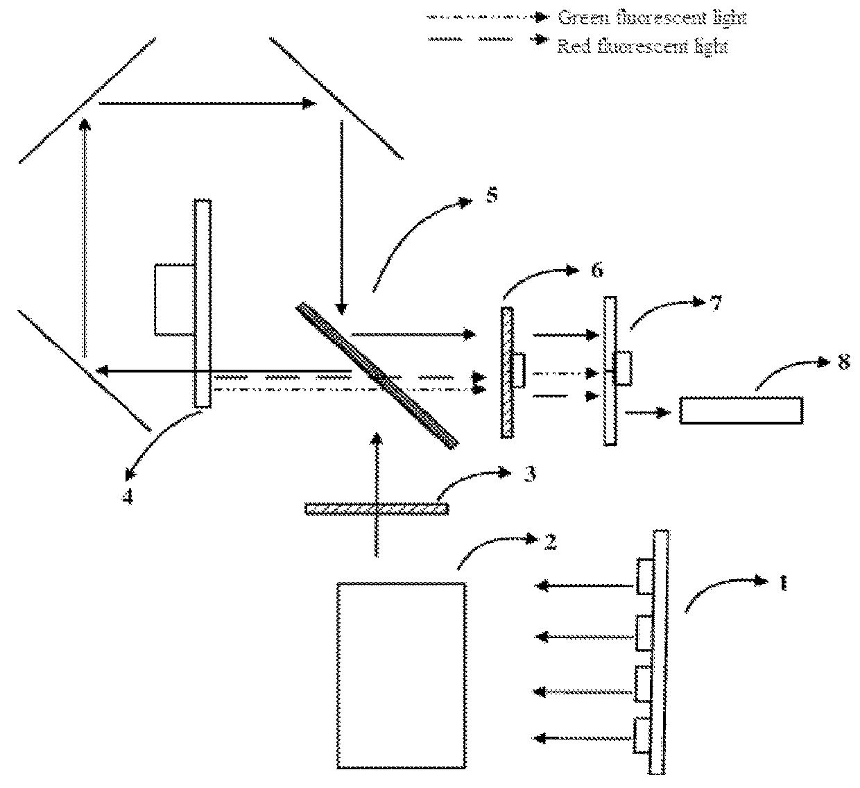
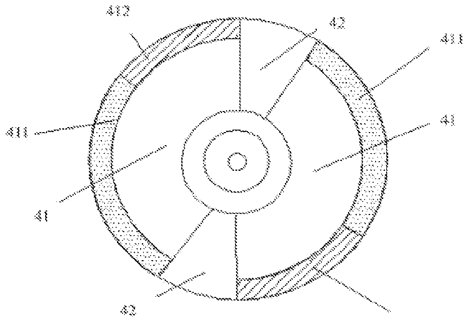
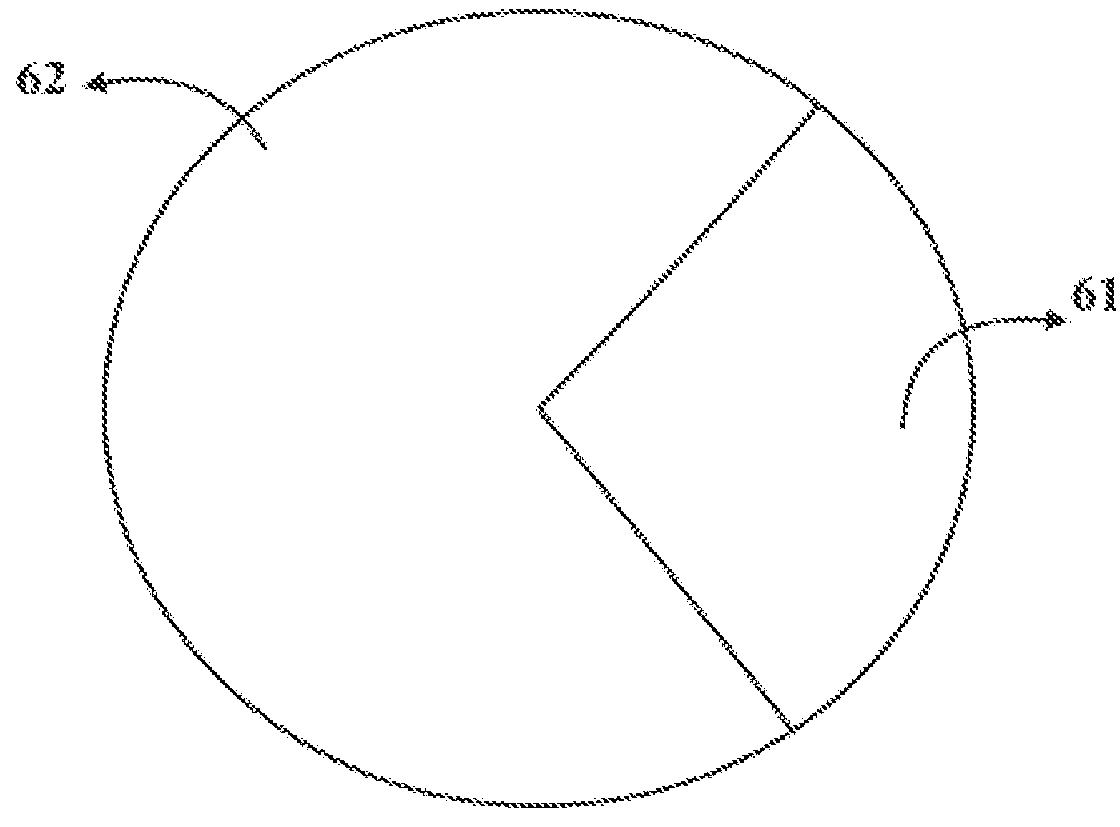
[0018]Some embodiments of the disclosure provides a laser light source. As shown in FIG. 1, the laser light source comprises a laser device 1, a first diffusion element 3, a fluorescence wheel 4 and a second diffusion element 6. The first diffusion element 3 is fixedly arranged in the optical path before the laser light transmits into the fluorescence wheel 4, so that the laser light emitted by the laser device 1 transmits the first diffusion element before reaching the fluorescence wheel 4. The las...


PUM


Abstract

A laser light source is disclosed that includes a laser device, a first diffusion element, a fluorescence wheel, and a second diffusion element. The fluorescence wheel emits a fluorescent light when excited by the laser light, and before reaching the fluorescence wheel, the laser light emitted by the laser device is transmitted through the first diffusion element that is fixedly arranged. As the second diffusion plate rotates about its axis, the laser light from the first diffusion element and the fluorescent light from the fluorescence wheel transmit through the second diffusion plate.

Description

CROSS-REFERENCE TO RELATED APPLICATION[0001]This application is a Continuation Application of PCT / CN2015 / 088942, filed Sep. 6, 2015, which claims priority to Chinese Patent Application No. 201510298364.7 filed on Jun. 3, 2015, titled “LASER LIGHT SOURCE AND PROJECTION DISPLAY DEVICE”, the entirety of each are hereby incorporated by reference herein.TECHNICAL FIELD[0002]The present disclosure relates to the field of projection display, in particular to a laser light source and a projection display device.BACKGROUND[0003]A laser light is a light source emitting monochromatic coherent beams, with high luminance and strong directionality. Owing to the numerous advantages, the laser light has been gradually applied as a light source in the technical field of projection display in recent years. However, because of the high coherence of the laserlight, the speckle effect is inevitable, such phenomenon is especially obvious in the solutions within which a pure laser light is used as the lig...

Claims


Application Information

Patent Timeline
IPC IPC(8): G03B21/20
CPCG03B21/208G03B21/204G03B21/2013G03B21/2066G02B5/0263G02B5/0278G02B26/008G02B27/48G03B33/08H04N9/3114H04N9/3161H04N9/3158H04N9/3164
Inventor TIAN, YOULIANGLIU, XIANRONGLI, WEI
Owner HISENSE
Why Eureka
Try Eureka