
Super-sonic diffuser for super-sonic vortex flow natural gas separator

A supersonic, diffuser technology, applied in the direction of the cyclone axial reversible device, cyclone device, etc., can solve the problem of the reduction of the pressure recovery ability of the supersonic cyclone separator, the energy loss, and the reduction of the diffuser. efficiency issues

Inactive Publication Date: 2007-10-17
曹学文
View PDF0 Cites 11 Cited by
  • Summary
  • Abstract
  • Description
  • Claims
  • Application Information

AI Technical Summary

Problems solved by technology

There is a strong shock wave phenomenon in the diffuser channel, which causes a large energy loss and reduces the diffusion efficiency of the diffuser; the air flow in the diffuser is a swirling flow with a large tangential velocity, which cannot be converted into The pressure energy will reduce the pressure recovery ability of the supersonic cyclone separator; at the same time, the pressure fluctuation will destabilize the shock wave at the inlet of the diffuser, and the shock wave will continue to move forward and enter the cyclone separation section, affecting the normal operation of the separator

Method used


Image

  • Super-sonic diffuser for super-sonic vortex flow natural gas separator
  • Super-sonic diffuser for super-sonic vortex flow natural gas separator
  • Super-sonic diffuser for super-sonic vortex flow natural gas separator

Examples


Embodiment Construction

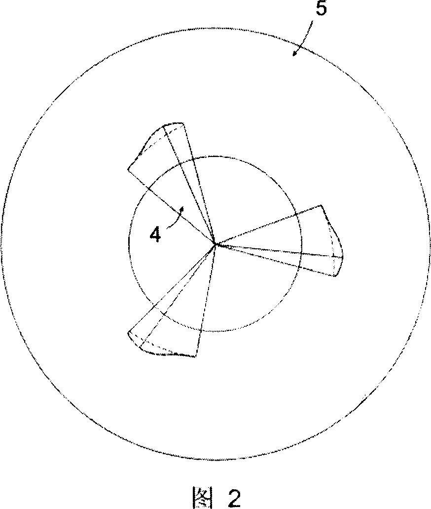
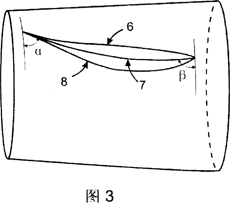
[0015] The accompanying drawing is an example of a typical supersonic diffuser designed and processed according to the purpose of the present invention. The separation section of the supersonic cyclone natural gas separator where the supersonic diffuser is located is a cylindrical shell. Fig. 1 is a front view of a supersonic diffuser, and Fig. 2 is a side view of a supersonic diffuser. The supersonic diffuser is composed of shrinkage pipe section 1 , straight pipe section 2 , arc-shaped wall surface expansion pipe section 3 , linear wall surface expansion pipe section 5 and guide fins 4 . In this example, the profile curve of the shrinking pipe section is a cubic polynomial, the inlet diameter is 17.7mm, the length is 15.3mm, the shrinkage angle is 30°, and the end tangent is parallel to the axial direction. The length of the expansion pipe section is 230.5mm, the expansion angle is 6°, and the radius of the curve of the arc section is 20 times the diameter of the straight s...


PUM


Abstract

The invention provides a supersonic velocity diffuser for a supersonic velocity rotational flow natural gas separator as an important component of the separator, wherein the diffuser is comprised of four parts of a contraction pipe part, a straight pipe part, an expansion pipe part and a diversion fin, wherein profile curve of the contraction pipe part is high order polynomial, profile curve of the expansion pipe part adopts circular arc adding straight line, while the parts are smoothly connected with each other to reduce disturbance of air current. Bottom surface of the diversion fin as a truncated cone surface corresponds with an inner wall of a panel pipe and is fixed on the inner wall. On the bottom surface, arc line is a high order polynomial curve, and the bottom surface profile thickness varies according to the high order polynomial law. Diversion fin top contraction becomes bout, parallel in axial straight line. Set up 2 -6 slices diversion fin in this supersonic velocity diffuser, may rotational flow natural gas circulation melts for axial flow, have higher expand to press efficiency, have the compression resistant force fluctuation than winner to disturb ability, can raise the step up ratio of supersonic velocity rotational flow natural gas separator, strengthen the applicability of supersonic velocity rotational flow natural gas separator. Top part of the diversion fin is contracted into a straight line parallel to an axial. 2-6 pieces of diversion fins are provided within the supersonic velocity diffuser for converting the rotational flow natural gas flow into an axial flow, which has higher efficiency of pressure expanding, stronger compression resistant force fluctuation capacity, can raise the step up ratio and applicability of the supersonic velocity rotational flow natural gas separator.

Description

Technical field [0001] The invention relates to a diffuser part of a supersonic cyclone natural gas separator - a supersonic diffuser, which belongs to the technical field of natural gas gathering, transportation, processing and treatment. Background technique [0002] The supersonic cyclone natural gas separator developed by supersonic cyclone separation technology is composed of Laval nozzle, supersonic rectifier tube, supersonic wing, diffuser tube and other components. It combines the theories of gas dynamics, thermodynamics and fluid mechanics. Expansion and cooling, cyclone gas / liquid separation, recompression and other processes are completed in a closed and compact device. The gas flow passes through the Laval nozzle and expands adiabatically to supersonic speed, forming a low temperature and low pressure. The low temperature causes the heavy hydrocarbons and water in the natural gas to condense and nucleate, and grow into small droplets to form a gas-liquid mixed fl...

Claims


Application Information

Patent Timeline
IPC IPC(8): B04C5/00
Inventor 曹学文杜永军
Owner 曹学文
Learn More