Capillary structure of heat plate

a technology of capillaries and heat plates, which is applied in the direction of indirect heat exchangers, lighting and heating apparatus, etc., can solve the problems of often large amount of heat generated by electronic devices, and achieve the effects of improving the temperature reduction efficiency of the heat plate, enhancing the uniformity of distribution of the working fluid, and increasing the diffusion efficiency of vapor of the working fluid

Inactive Publication Date: 2012-02-09
KUNSHAN JUZHONG ELECTRONICS
View PDF5 Cites 11 Cited by
  • Summary
  • Abstract
  • Description
  • Claims
  • Application Information

AI Technical Summary

Benefits of technology

[0005]A primary objective of the present invention is to provide a capillary structure of a heat plate that improves temperature reduction efficiency of the heat plate.
[0006]To realize the above objectives, the present invention provides a heat plate comprising two boards, which mate and are coupled to each other to define therebetween an accommodation chamber, at least one first capillary layer received in the accommodation chamber, and at least one second capillary layer received in the accommodation chamber in such a way that the first and second capillary layers are stacked over each other. With the arrangement of the first and second capillary layers, the efficiency of diffusion of vapor of a working fluid is increased and the uniformity of distribution of the working fluid is enhanced, so that the efficiency of temperature reduction is improved to thereby offer practicability, novelty, improvement, and convenience.

Problems solved by technology

An electronic device often generates a great amount of heat during a long term operation.

Method used


Image

  • Capillary structure of heat plate
  • Capillary structure of heat plate
  • Capillary structure of heat plate

Examples


Embodiment Construction

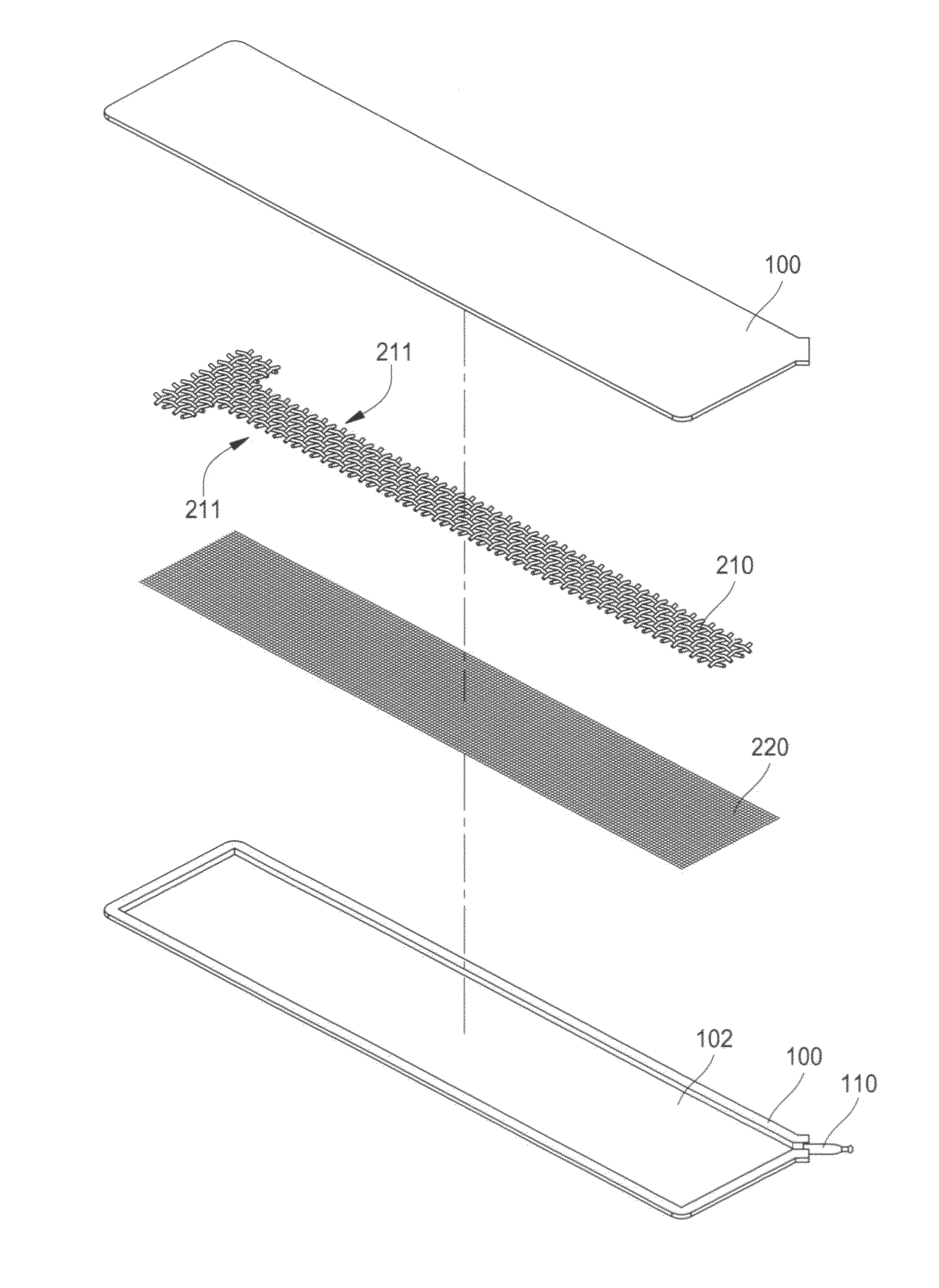
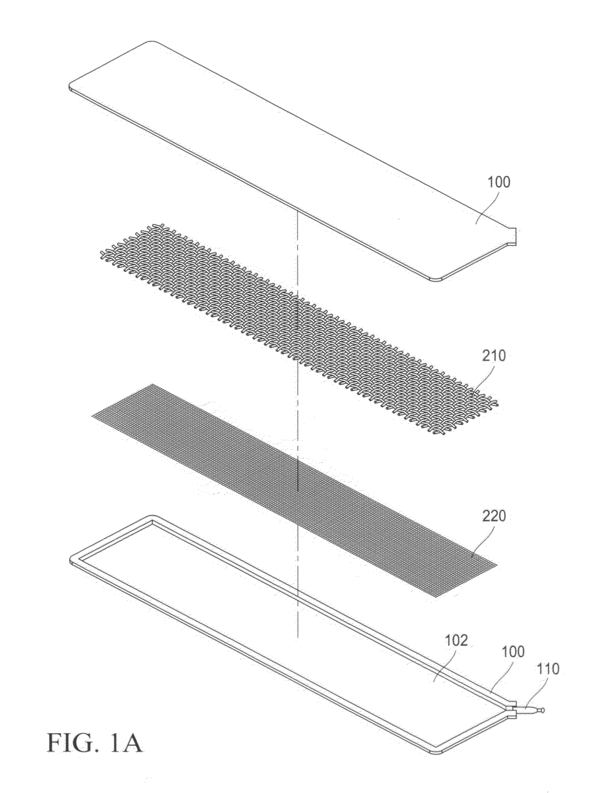
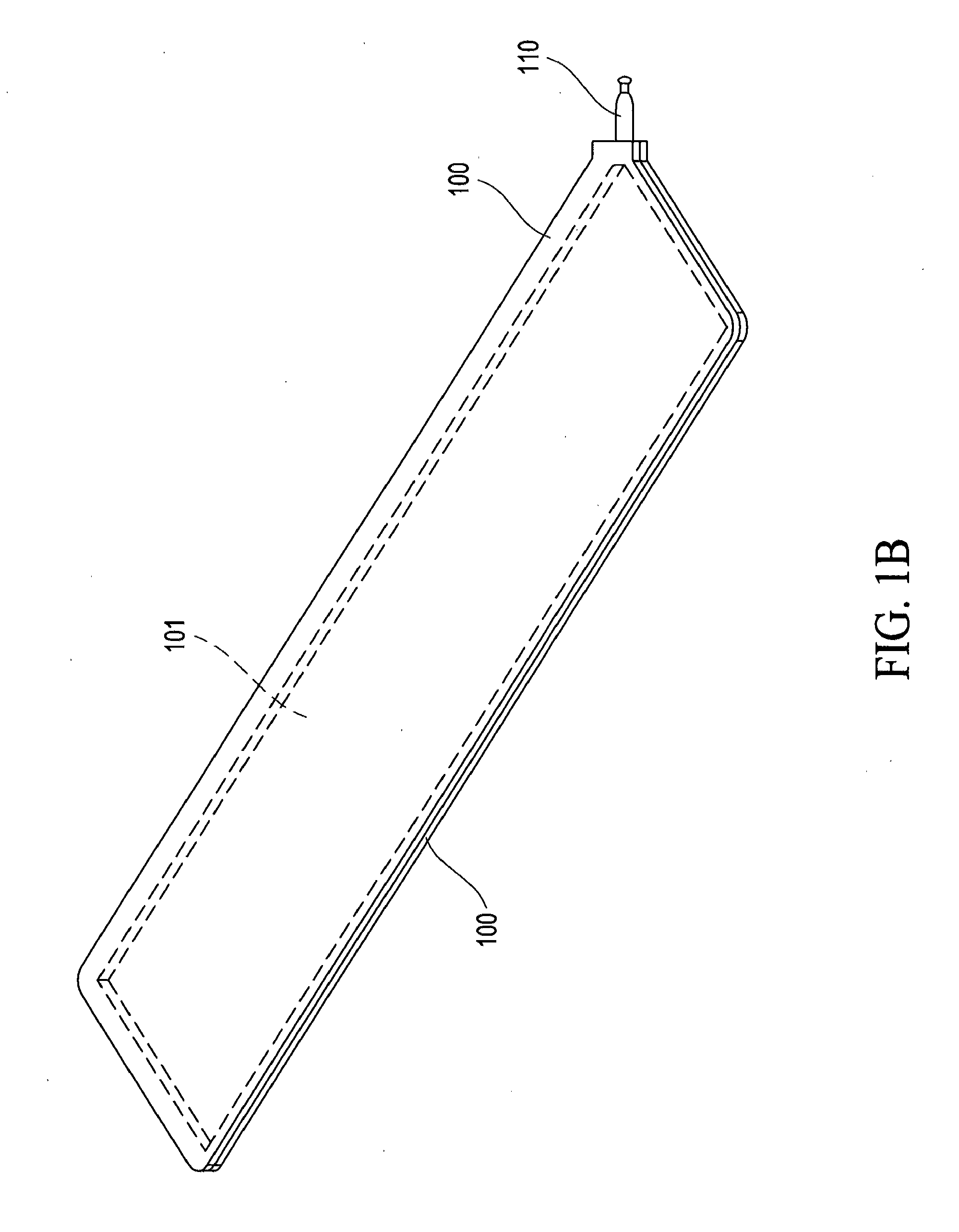
[0018]With reference to the drawings and in particular to FIGS. 1A-1D, which respectively show an exploded view of a heat plate according to a first embodiment of the present invention, a perspective view illustrating two boards of the heat plate coupled together, a perspective of the heat plate, and a cross-sectional view of the heat plate, the heat plate constructed in accordance with the present invention comprises two boards 100, a sealing tube 110, at least one first capillary layer 210, and at least one second capillary layer 220 and realizes functions of lowering temperature of a heat source, performing effective transfer of heat, and improving temperature reduction efficiency.

[0019]The two boards 100 are mated and coupled to each other so that the two boards 100 defined an accommodation chamber 101 therebetween. In a practical arrangement, one of the two boards 100 is structured to form a recess 102, or alternatively, both boards 100 are structured to form corresponding rece...


PUM


Abstract

A heat plate includes two boards, which mate and are coupled to each other to define therebetween an accommodation chamber and a capillary structure of at least one first capillary layer and at least one second capillary layer arranged in the accommodation chamber in such a way that the first and second capillary layers are stacked over each other. With the arrangement of the first and second capillary layers, the efficiency of diffusion of vapor of a working fluid is increased and the uniformity of distribution of the working fluid is enhanced, so that the efficiency of temperature reduction is improved.

Description

FIELD OF THE INVENTION[0001]The present invention relates to a structure of heat plate, and in particular to a capillary structure of a heat plate applicable to an electronic device.BACKGROUND OF THE INVENTION[0002]An electronic device often generates a great amount of heat during a long term operation. A common solution for handling such a great amount of heat is installation of a heat plate that dissipates the heat. A heat plate is advantageous in respect of high heat conductivity, light weight, and simple construction and can carry out transfer of a large amount of heat without consuming electrical power.[0003]A conventional heat plate structurally comprises a board, which has a hollow interior forming a chamber that receives and retains therein a capillary tissue and is filled with a working fluid. Connected to one side of the board is a sealing tube (or referred to an opening sealing tube, a degassing tube, or a filling and degassing tube), which has an end mounted to the board...

Claims


Application Information

Patent Timeline
Patent Type & Authority Applications(United States)
IPC IPC(8): F28D15/00
CPCF28D15/046
Inventor HUANG, YU-POKUO, TUNG-JUNG
Owner KUNSHAN JUZHONG ELECTRONICS
Why Eureka
Try Eureka