Method and device for processing precise time transfer protocol message

A message processing and precise time technology, applied in the field of mobile communication, can solve the problems of PTP message looping and achieve the effect of preventing looping

Inactive Publication Date: 2009-12-30
GLOBAL INNOVATION AGGREGATORS LLC
View PDF0 Cites 19 Cited by
  • Summary
  • Abstract
  • Description
  • Claims
  • Application Information

AI Technical Summary

Problems solved by technology

[0005] In view of this, the present invention provides an improved PTP message processing method and device to solve the probl

Method used


Image

  • Method and device for processing precise time transfer protocol message
  • Method and device for processing precise time transfer protocol message
  • Method and device for processing precise time transfer protocol message

Examples


Embodiment 1

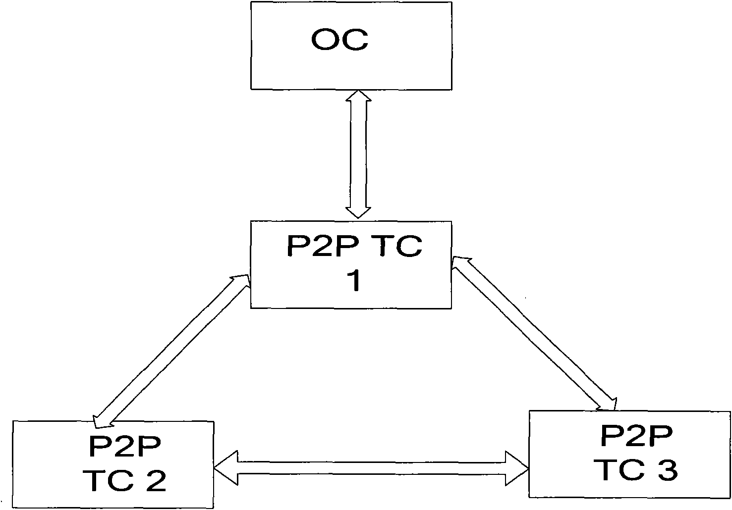
[0042] This embodiment takes figure 2 Take the network composed of transparent clocks shown as an example for illustration, such as figure 2 As shown, in this network, the port connected to the ordinary clock (OC) and the P2P transparent clock (P2P TC) 1 acts as the master (MASTER) port, and actively initiates the PTP synchronization message (Sync) message and the PTP point-to-point delay Request message (Pdelay_Rep), and respond to Pdelay_Req message. exist figure 2 All connected ports on the P2P transparent clock (P2P TC) will forward the Syn message, actively initiate the Pdelay_Rep message, and respond to the Pdelay_Req message.

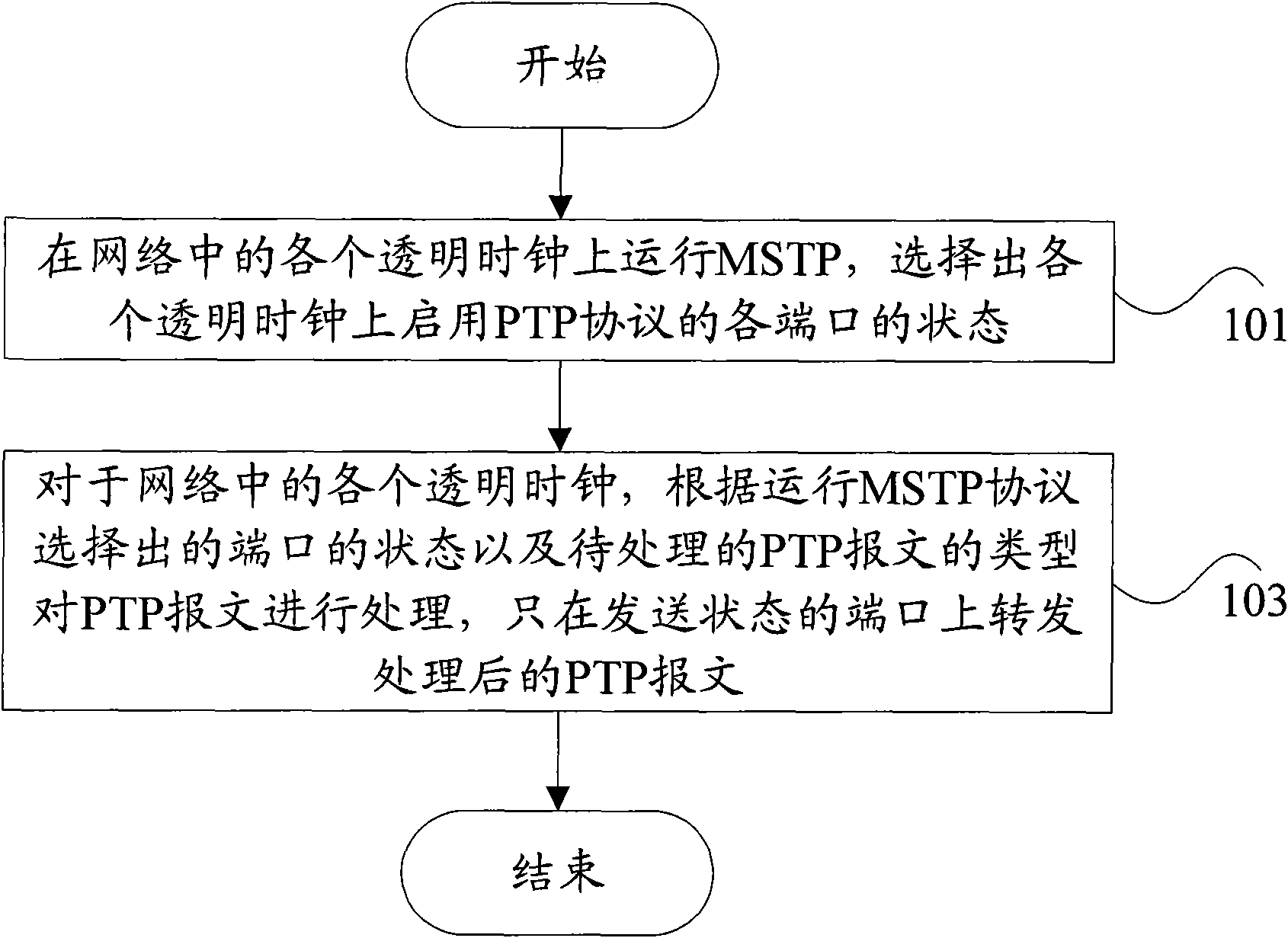
[0043] exist figure 2 Three P2P TCs form the PTP message loop, then according to the PTP message processing method of the embodiment of the present invention, the network in the present embodiment is processed as follows:

[0044] (1) MSTP protocol is enabled on all P2P transparent clocks in the figure, an instance is created, and the VLA...

Embodiment 2

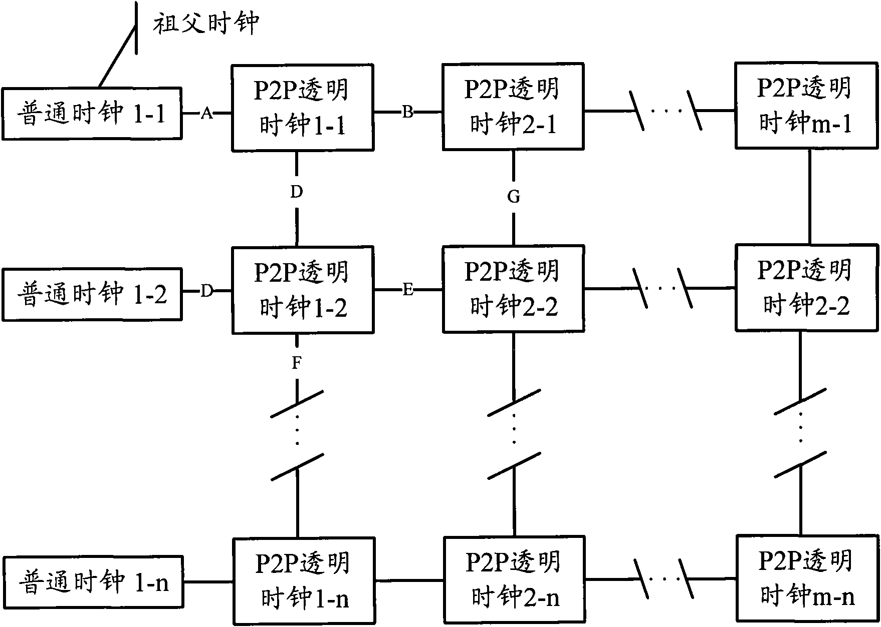
[0048] This embodiment takes image 3 The shown mesh network is taken as an example to illustrate the technical solutions provided by the embodiments of the invention. Specifically, it mainly includes the following processing steps:

[0049] In step 1, the port of the ordinary clock 1-1 on link A as the grandfather clock acts as the MASTER port, actively initiates a Sync message and a Pdelay_Rep message, and responds to a Pdelay_Req message.

[0050] Other ordinary clocks in the figure are used as slave clocks, and the time is synchronized with ordinary clock 1-1;

[0051] Step 2: After receiving the Sync message on link A, the P2P transparent clock 1-1 forwards it to two links B and C; after receiving the Pdelay_Req message, it sends it to the PTP protocol stack module for processing, and the node clock Pdelay_Req messages are sent on links A, B and C.

[0052] The processing of other P2P transparent clocks in the figure is similar to that of P2P transparent clock 1-1, and...

Embodiment 3

[0059] This embodiment takes Figure 4 The network structure shown is taken as an example to describe the technical solutions provided by the embodiments of the present invention. Such as Figure 4 shown in Figure 4 In the shown network, devices 1 and 2 of the convergence ring are set to the boundary clock function, devices 3, 4 and 5 are set to the transparent clock function (for example, P2P transparent clock), and all devices on the access ring are set to the transparent clock function (for example, P2P transparent clock). Moreover, a TD base station is connected to the access ring equipment, and each TD base station has a common clock function. All PTP devices use the one-step clock mode defined by 1588v2.

[0060] According to the technical solution provided by the embodiment of the present invention, for Figure 4 In the shown network, the network is a PTP clock domain, and the domain delay measurement mechanism is the Peer delay mode, and the network is also an MS...


PUM


Abstract

The invention discloses a method and a device for processing a precise time transfer protocol message. The method is used for processing a PTP message in a looped network consisting of transparent clocks; the method comprises the following steps: operating a multiple spanning tree protocol MSTP in each transparent clock of the network; selecting the state of each port starting a PTP protocol in each transparent clock; according to the state of the port selected through operation of the MSTP protocol and the type of the PTP message to be processed, processing the PTP message; and forwarding the processed PTP message only in the port with a sending state. According to the method and the device, the looping of the PTP message can be prevented.

Description

technical field [0001] The invention relates to the technical field of mobile communication, in particular to a method and device for processing a precise time transfer protocol message. Background technique [0002] At present, there are two types of synchronization between devices in a communication network: one is frequency synchronization, that is, the signals at the source end and the destination end maintain a certain relationship in frequency or phase. Frequency synchronization can also be called clock synchronization, for example , Synchronous Ethernet, E1 interface clock synchronization, etc.; another kind of synchronization is time synchronization, that is, the source and destination not only have the same frequency, but also the same phase, and have the same time scale. [0003] The frequency synchronization can be realized by each network element node sequentially locking a clock synchronization signal (such as synchronous Ethernet, etc.). The clocks of each net...

Claims


Application Information

Patent Timeline
IPC IPC(8): H04L29/06H04L12/56H04L7/00
CPCH04J3/0658H04J3/0679H04J3/0667H04L43/106H04L41/0213
Inventor 杨元永宿飞
Owner GLOBAL INNOVATION AGGREGATORS LLC
Why Eureka
Try Eureka