Check patentability & draft patents in minutes with Patsnap Eureka AI!

Stopper structure, and its manufacturing method

A manufacturing method and stopper technology, which are used in manufacturing tools, casting equipment, casting melt containers, etc., can solve the problems of gas leakage, unstable shaft and rod fixing, and inability to ensure gas tightness, so as to improve the joining accuracy, The effect of improving operation efficiency and preventing gas leakage

Inactive Publication Date: 2009-12-30
KROSAKI HARIMA CORP
View PDF1 Cites 0 Cited by
  • Summary
  • Abstract
  • Description
  • Claims
  • Application Information

AI Technical Summary

Problems solved by technology

However, even if such a small-expansion shaft joint part is inserted in advance, when a metal mandrel is joined there, there is a possibility that the shaft joint part may be crushed due to its thermal expansion, and the The length in the vertical direction of the shaft is elongated to cause looseness between the shaft rod and the stopper refractory, making the fixing of the shaft relative to the stopper refractory unstable, and the gas tightness between them cannot be ensured. As a result, the problem of gas leakage cannot be improved
[0015] When looseness occurs between the shaft rod and the stopper refractory due to the elongation of the vertical length of the shaft rod, it is necessary to manually perform so-called tightening, and tighten the bolts continuously during the operation to eliminate the looseness. Since it is done manually and continuously, it is difficult to completely eliminate the gap or looseness, which is also an operational problem
[0016] In this way, it is still impossible to provide a stopper structure that has a structure that does not loosen and does not leak gas during use, and does not need to be tightened.

Method used


Image

  • Stopper structure, and its manufacturing method
  • Stopper structure, and its manufacturing method
  • Stopper structure, and its manufacturing method

Examples


Embodiment 1

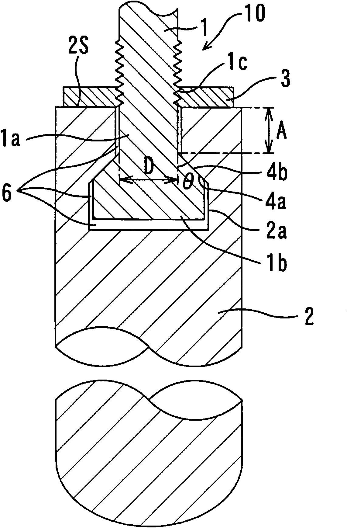
[0058] figure 1 It is a cross-sectional view showing an example of the stopper structure of the present invention.

[0059] exist figure 1 In the shown stopper structure 10 , the tip end of the metal shaft 1 is attached to the installation hole 2 a of the stopper refractory 2 via the space 6 as the expansion absorption margin of the tip end of the shaft 1 .

[0060] The distal end portion of the shaft rod 1 has a stepped structure having a small-diameter portion 1a on the base end side and a large-diameter portion 1b larger than the small-diameter portion on the distal end side, and a first tapered surface is formed between the small-diameter portion 1a and the large-diameter portion 1b. 4a. On the other hand, the mounting hole 2a of the stopper refractory 2 has a shape similar to the tip portion of the shaft rod 1, and has a second tapered surface 4b superimposed on the first tapered surface 4a on its inner surface.

[0061]In addition, the shaft rod 1 is provided with a...

Embodiment 2

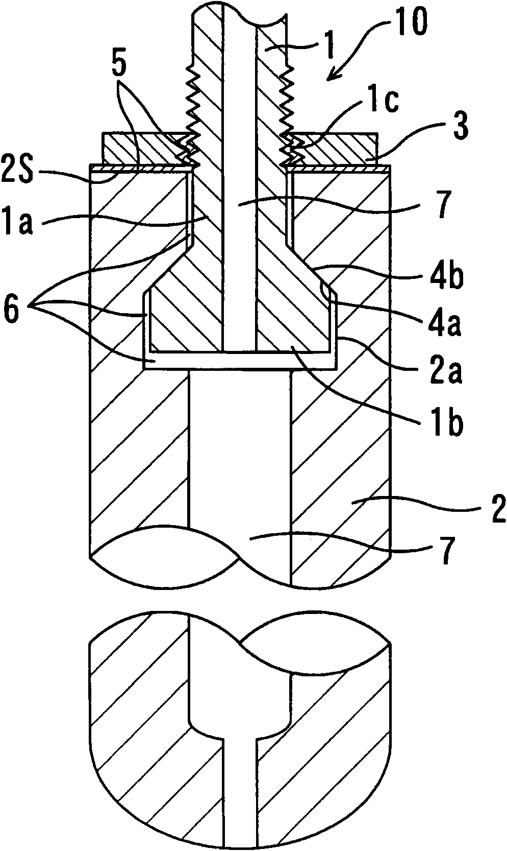
[0066] figure 2 is a sectional view showing another example of the stopper structure of the present invention. In this embodiment, the gas flow path 7 is provided inside the stopper structure 10 . In addition, coordination of the shaft rod 1 and the stopper refractory 2, connection structure, etc. are the same as those of the first embodiment.

[0067] In this embodiment, the gas flow path 7 for conducting gas to the installation hole 2 a of the stopper refractory 2 is provided inside the shaft rod 1 , and the secondary installation hole 2 a is provided inside the stopper refractory 2 . The gas flow path 7 penetrating to the top end is either blown into the molten metal from the top end of the stopper refractory, or the gas is passed through the gas flow path 7 for air-cooling the shaft rod 1 .

[0068] In this way, in this embodiment, the gas flow path 7 for conducting gas is provided inside the shaft rod 1 and the stopper refractory 2, so in order to improve the gas tight...

Embodiment 3

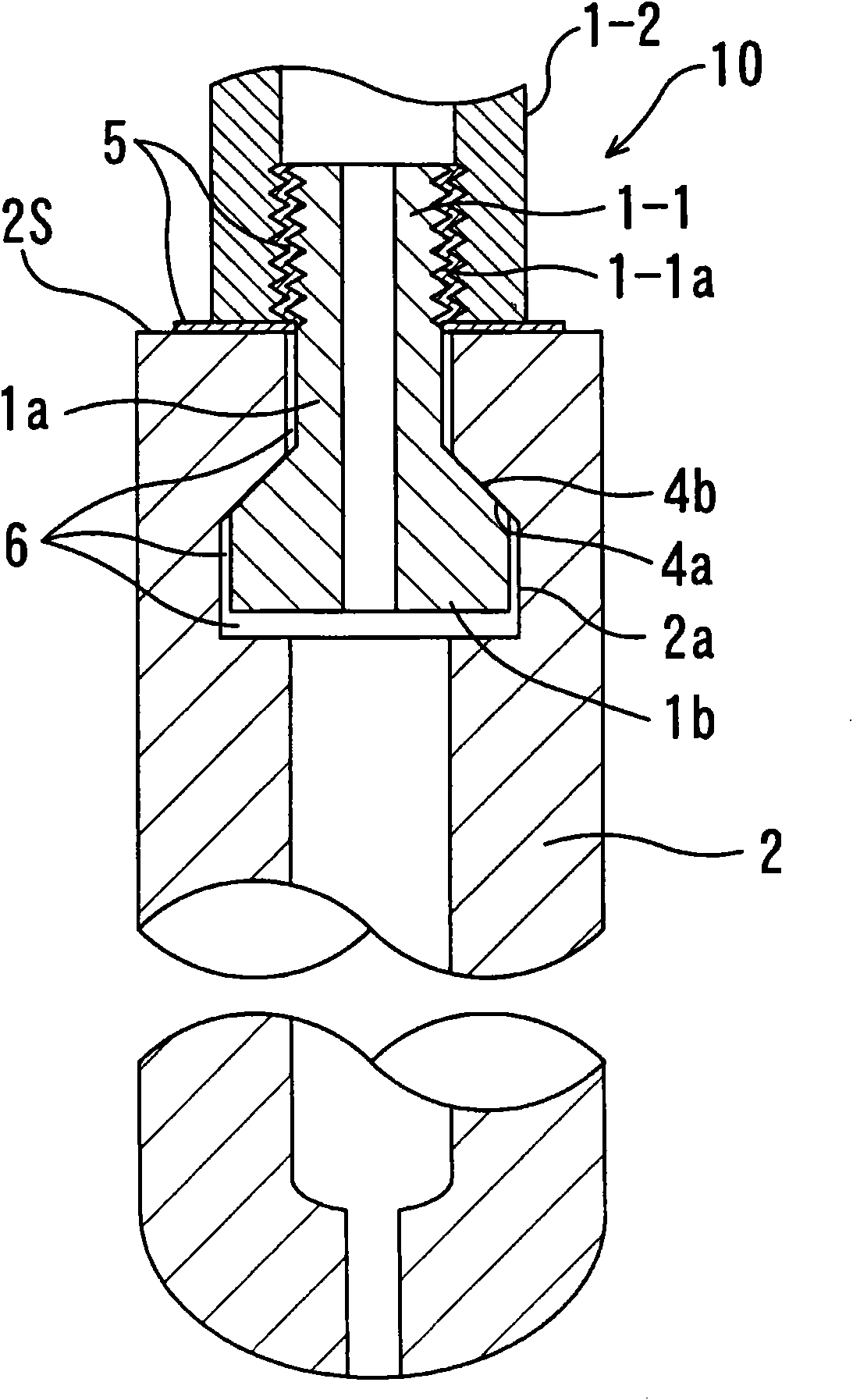
[0074] image 3 It is a sectional view showing still another example of the stopper structure of the present invention. This embodiment is an example in which the shaft 1 is divided into a first shaft portion 1-1 and a second shaft portion 1-2.

[0075] The first shaft part 1-1 is installed in the mounting hole 2a of the stopper refractory 2 at the top end thereof, on the outside above the upper end surface 2S of the stopper refractory of the first shaft part 1-1. A threaded portion 1-1a is formed. Then, the second shaft rod part 1-2 is screwed onto the threaded part 1-1a, and the lower end face of the second shaft rod part 1-2 is aligned with the upper end surface 2S of the stopper refractory by screwing it in. The upper end surface 2S of the stopper refractory is in contact, and the first shaft rod part 1-1 rises, and the surfaces of the first tapered surface 4a and the second tapered surface 4b overlap and stick together, so that the first shaft rod part 1-1 and the secon...


PUM


Abstract

The present invention provides a stopper structure capable of preventing loosening of a shaft rod during use, and gas leakage which is likely to occur when the stopper structure is designed to allow gas to pass therethrough. The shaft rod 1 is adapted to be mounted in a mounting hole 2a of a refractory stopper 2, and formed to have an outer peripheral surface including a first tapered sub-surface 4a which increases in diameter toward an axially lower edge of the shaft rod. The mounting hole 2a of the refractory stopper 2 is formed to have an inner surface including a second tapered sub-surface 4b adapted to come into surface contact with the first tapered sub-surface 4a. The shaft rod 1 is adapted to be fastened to the refractory stopper so as to allow the first tapered sub-surface 4a to be brought into close surface contact with the second tapered sub-surface 4b. The distal end of the shaft rod 1 is formed in a configuration satisfying the following relation: tan theta <= D / 2A, wherein: A is a length of the shaft rod 1 between a position of the shaft rod 1 corresponding to an upper edge surface 2S of the refractory stopper, and a start position of the first tapered sub-surface 4a; D is an outer diameter of the first tapered sub-surface 4a at the start position; and theta is a taper angle of the first tapered sub-surface 4a.

Description

technical field [0001] The present invention relates to a stopper structure used to start or stop the discharge of molten metal from a container through a nozzle, or to control the flow rate (hereinafter simply referred to as "discharge control"). A stopper structure in which a shaft for connecting it to a driving device is mounted on a stopper refractory and a method for manufacturing the same. Background technique [0002] As a discharge control method when molten metal is discharged from the container through the nozzle, there is an operation method of opening and closing the space of the fitting portion with the upper end of the nozzle using a stopper structure provided inside the container. [0003] The stopper structure is generally formed of an integral stopper refractory that is impregnated with molten metal, and a metal shaft is mounted on the top of the stopper refractory that is not immersed in molten metal, and the shaft is connected to the drive unit used. In ...

Claims


Application Information

Patent Timeline
Patent Type & Authority Applications(China)
IPC IPC(8): B22D41/18
CPCB22D41/18B22D41/186
Inventor 船渡淳一东崇广
Owner KROSAKI HARIMA CORP
Features
  • R&D
  • Intellectual Property
  • Life Sciences
  • Materials
  • Tech Scout
  • Unparalleled Data Quality
  • Higher Quality Content
  • 60% Fewer Hallucinations
Learn More