Supercharge Your Innovation With Domain-Expert AI Agents!

Image processing device, image processing method, and image processing program

An image processing device and image technology, applied in the field of image processing, can solve problems such as inability to obtain clear images, shaking, and unnatural embossment

Active Publication Date: 2009-12-30
FUJITSU LTD
View PDF2 Cites 10 Cited by
  • Summary
  • Abstract
  • Description
  • Claims
  • Application Information

AI Technical Summary

Problems solved by technology

[0010] By generating a difference image of two images continuously captured in synchronization with the flickering timing of the lighting, the background behind the captured subject is removed, the influence of disturbing light is removed, and an image in which only the subject is clearly captured is generated, in In this case, if the subject moves slightly between the images used to obtain the difference, even if the difference image is generated, the subject will be shaken, or unevenness will be emphasized unnaturally, and there is a problem that a clear image cannot be obtained.

Method used


Image

  • Image processing device, image processing method, and image processing program
  • Image processing device, image processing method, and image processing program
  • Image processing device, image processing method, and image processing program

Examples


no. 1 Embodiment approach

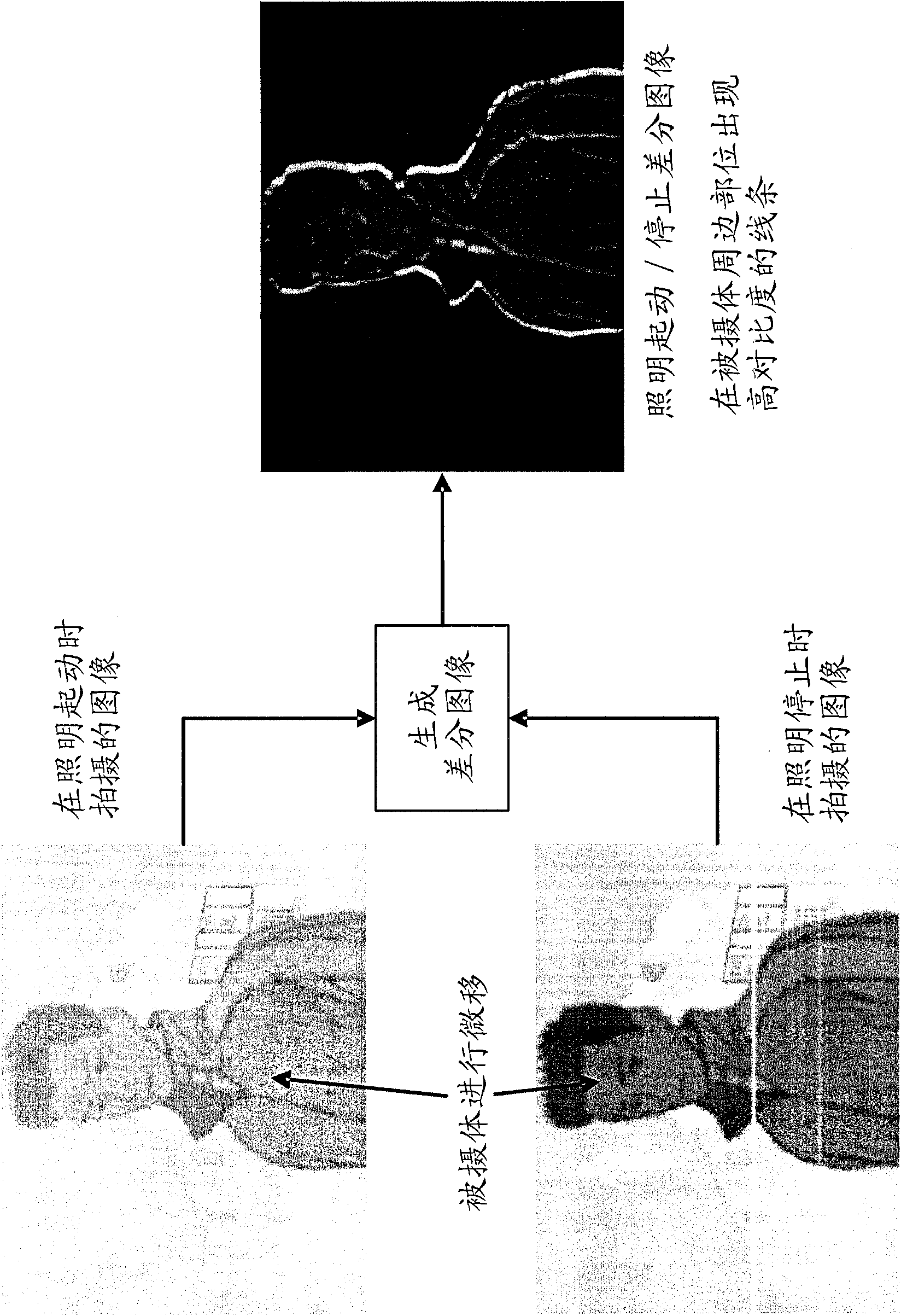
[0046] First, a first embodiment of the present invention will be described. In this embodiment, the following phenomenon is utilized: when a difference image is generated between two images captured continuously, and the subject moves during the shooting interval of these images, the outline of the subject in the difference image Partially and on the inner side of this outline, pixel areas with higher brightness appear.

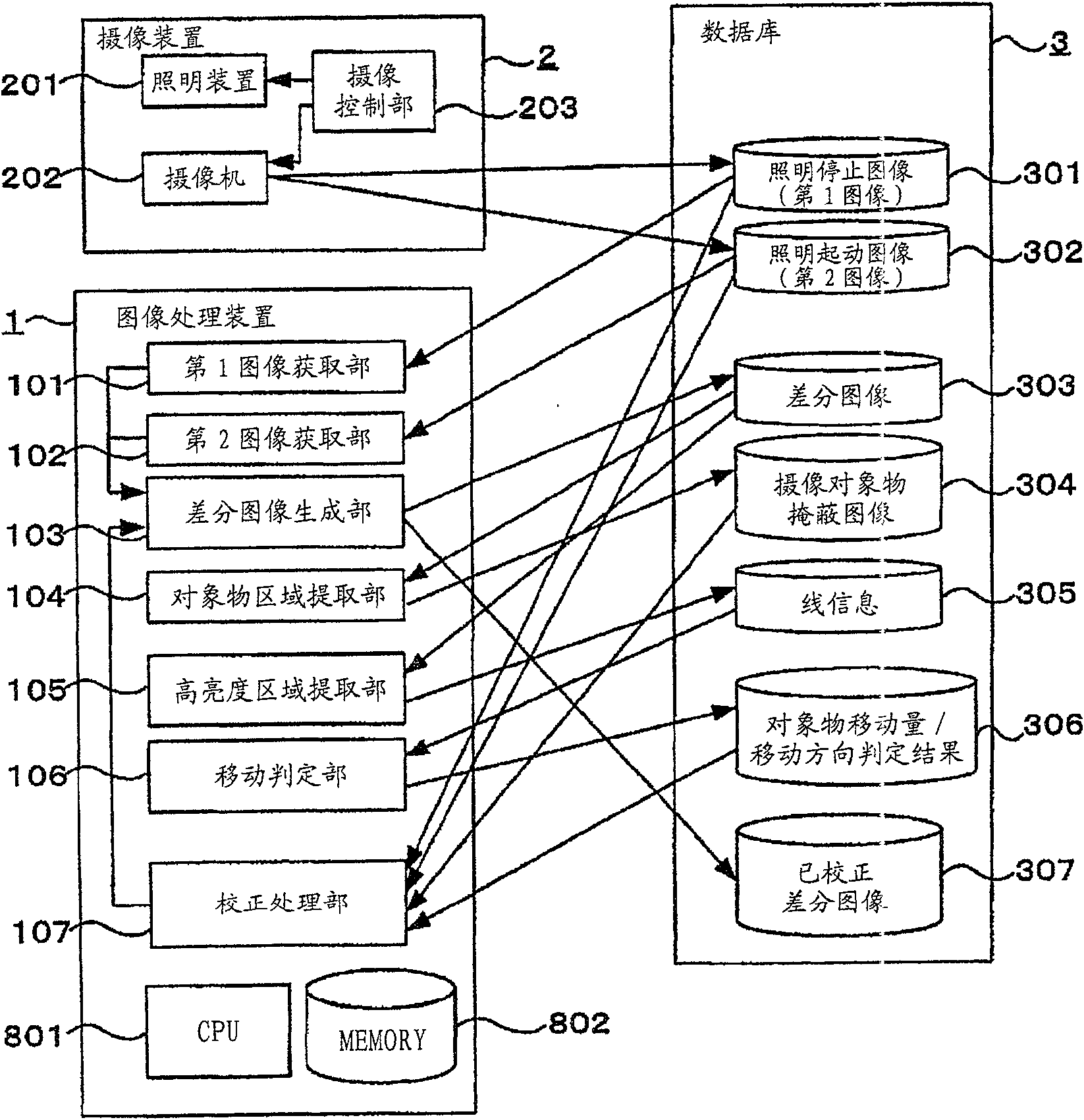
[0047] figure 1 It is a functional block diagram illustrating the configuration of the image processing device according to the first embodiment of the present invention. The image processing device 1 of the present embodiment can acquire image data obtained by imaging an imaging target object by the imaging device 2 . Here, the image data captured by the imaging device 2 is stored in the database 3 , and the image processing device 1 refers to the database 3 to acquire the image data. The image processing device 1, the imaging device 2, and the database ...

no. 2 Embodiment approach

[0106] Next, a second embodiment of the present invention will be described. This embodiment is a modified example of the first embodiment described above. Hereinafter, components having the same functions as those already described in the first embodiment are given the same reference numerals, and description thereof will be omitted.

[0107] Figure 25 It is a functional block diagram for explaining the configuration of the image processing device 1' according to the second embodiment of the present invention. The image processing device 1' of this embodiment further includes a block matching processing unit 108 in addition to the configuration of the image processing device 1 of the first embodiment.

[0108] In the image processing device 1' of the present embodiment, the correction processing unit 107 corrects the position and size of the pixel region extracted by the object region extraction unit on the image based on the amount of movement determined by the movement d...

no. 3 Embodiment approach

[0116] Next, a third embodiment of the present invention will be described. This embodiment is a modified example of the first embodiment described above. Hereinafter, components having the same functions as those already described in the first embodiment are given the same reference numerals, and description thereof will be omitted.

[0117] Figure 27 It is a functional block diagram for explaining the configuration of the image processing device 1" according to the third embodiment of the present invention. The image processing device 1" according to the present embodiment has the configuration of the image processing device 1 according to the first embodiment and further includes pixel Select section 109 .

[0118] The pixel selection unit 109 selects only the pixels in the outline of the pixel region extracted by the object area extraction unit 104 or the pixels existing inside the outline.

[0119] The movement determination unit 106 determines the movement amount and...


PUM


Abstract

The invention provides an image processing device, image processing method, and image processing program. The image processing device comprises: a first image obtaining unit (101) for obtaining a first image which is obtained by imaging an object to be imaged at the time of non illumination in which the object to be imaged is not illuminated, a second image obtaining unit (102) for obtaining a second image which is obtained by imaging the object to be imaged at the time of illumination in which the object to be imaged is illuminated, a difference image generating unit (103) for generating a difference image which is composed of the difference between the luminance of each pixel in the first image obtained by the first image obtaining unit (101) and the luminance of each pixel in the second image obtained by the second image obtaining unit (102), a high luminance area extraction unit (105) for extracting the image area that is composed of pixels having higher luminances than a predetermined luminance value in the difference image generated by the difference image generating unit (103), and a movement determination unit (106) for determining the amount of movement of the object to be imaged from the timing when the first image is obtained to the timing when the second image is obtained in the image area extracted by the high luminance area extraction unit (105) are included.

Description

technical field [0001] The present invention relates to an image processing technique based on an image obtained by photographing the subject to be photographed during non-illumination when the subject is not illuminated, and an image obtained by photographing the subject under illumination when the subject is illuminated. , and extract the imaging target object on the captured image. Background technique [0002] Based on the purpose of monitoring and authentication, when shooting a subject entering the field of view through fixed-point observation, it is sometimes necessary to remove the background around the subject to form an image that only extracts the subject. [0003] Therefore, there is known a technique (hereinafter referred to as illumination start / stop difference) that blinks an illumination device for illuminating a subject entering the field of view of a camera, performs imaging in synchronization with the blinking timing of the illumination, and obtains the T...

Claims


Application Information

Patent Timeline
IPC IPC(8): H04N7/18
CPCH04N7/18H04N7/26G06T2207/10152G06T2207/20224G06T2207/30196G06T7/11G06T7/12G06T7/155G06T7/174G06T7/194G06T7/00H04N5/262
Inventor 福田充昭浜壮一青木隆浩
Owner FUJITSU LTD
Features
  • R&D
  • Intellectual Property
  • Life Sciences
  • Materials
  • Tech Scout
  • Unparalleled Data Quality
  • Higher Quality Content
  • 60% Fewer Hallucinations
Learn More