Heat exchange device
A technology of heat exchange device and heat exchanger, which is applied in the direction of lighting and heating equipment, evaporator/condenser, refrigeration components, etc., and can solve the problem of low heat exchange performance of the second heat exchanger 12, which affects the heat exchange device Overall heat transfer performance, low heat transfer coefficient of vapor refrigerant, etc., achieve the effect of reducing processing cost, low processing cost, and avoiding resistance
Active Publication Date: 2011-01-05
SANHUA(HANGZHOU) MICRO CHANNEL HEAT EXCHANGER CO LTD
View PDF0 Cites 0 Cited by
- Summary
- Abstract
- Description
- Claims
- Application Information
AI Technical Summary
Problems solved by technology
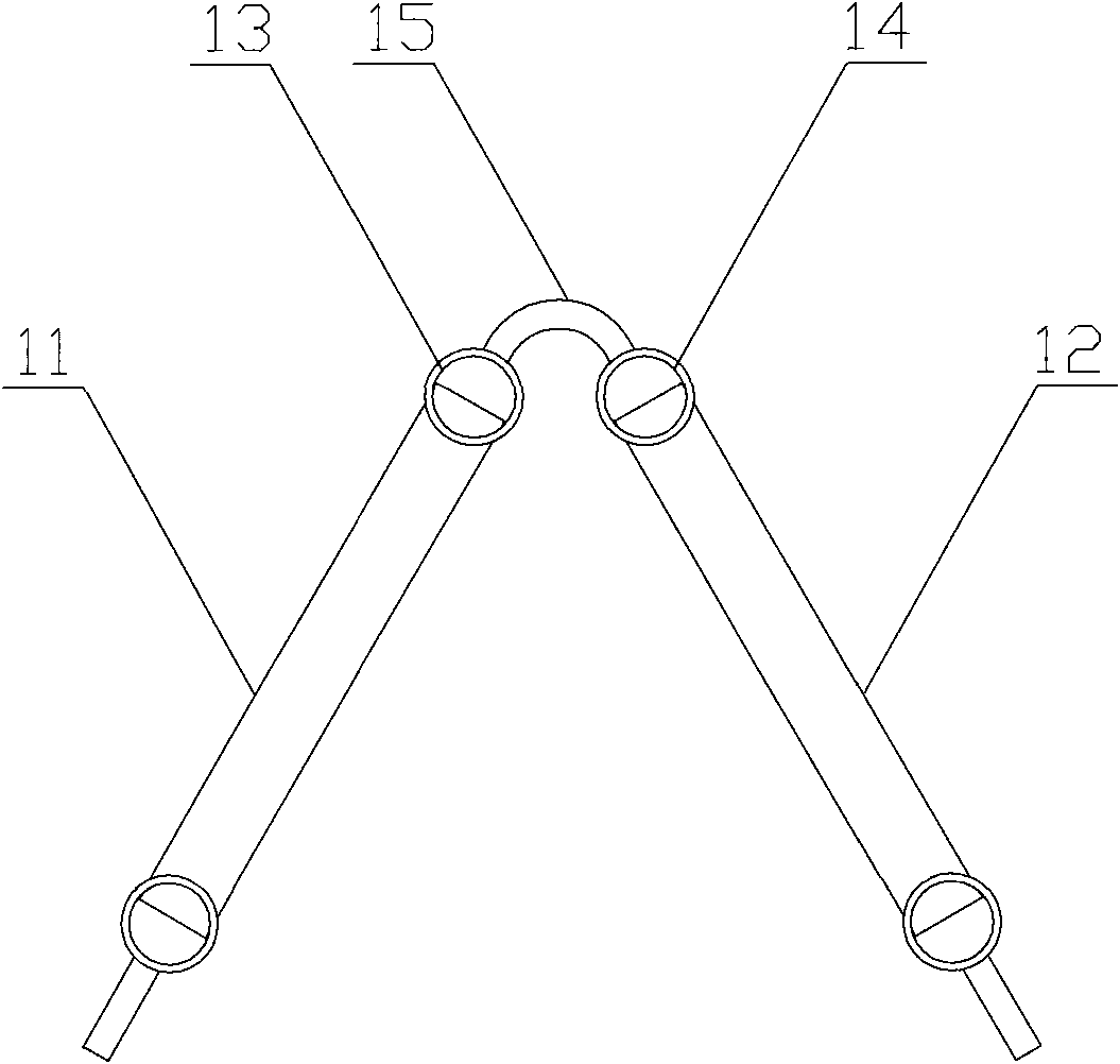
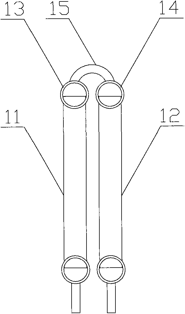
The refrigerant inside the heat exchanger is generally in a two-phase state, which is a liquid state and a vapor state; when the refrigerant enters the first header 13, the liquid refrigerant will stay at the bottom of the first header 13, while the vapor state The refrigerant enters the second header 14 through the connecting pipe 15, causing the refrigerant inside the second heat exchanger 12 to be basically in a vapor state, because the heat transfer coefficient of the vapor refrigerant is much lower than that of the liquid refrigerant The heat transfer coefficient causes the heat exchange performance of the second heat exchanger 12 to be lower than that of the first heat exchanger 11, thereby affecting the overall heat exchange performance of the heat exchange device
In addition, the pipe diameter of the connecting pipe 15 is significantly smaller than the pipe diameters of the first header 13 and the second header 14, so that the refrigerant will be subject to greater local resistance during the flow process, thereby increasing the refrigerant side pressure drop
Method used
View moreImage
Smart ImageViewing Examples

Examples
Embodiment Construction
Login to View More PUM
 Abstract
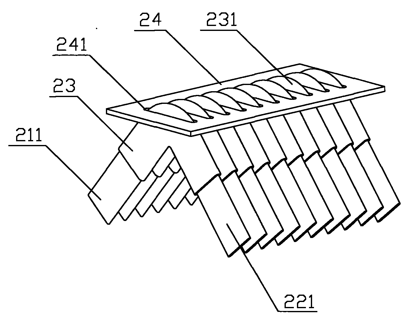
The invention discloses a heat exchange device comprising at least two heat exchangers which are sequentially connected. All heat exchangers comprise flat pipes with equal number and a plurality of pipe sleeves. The flat pipes of any one of the heat exchanger are hermetically connected with the flat pipes with opposite positions in the adjacent heat exchangers by the pipe sleeves. The flat pipes of the heat exchange device are directly connected by the pipe sleeves; and the method can ensure even distribution of refrigerant in each heat exchanger and reduce the lateral pressure drop of the refrigerant, thereby improving the whole heat exchange performance; in addition, the heat exchange device has low production cost and is conveniently installed.
Description
a heat exchange device technical field The invention relates to the technical field of refrigeration, in particular to a heat exchange device. Background technique Refrigeration devices generally include basic components such as condensers, evaporators, compressors, and throttle valves. The above-mentioned basic components are connected in sequence through pipelines to form a closed system. The refrigerant circulates in this closed system and undergoes state changes. Exchange heat with the outside to achieve cooling effect. Among the basic components included in the refrigeration device, the condenser and the evaporator are heat exchange components, and their structures are basically the same, and can be collectively referred to as heat exchangers. The heat exchange device in the prior art is composed of at least two heat exchangers connected in sequence, for example, a heat exchange device composed of two heat exchangers connected in sequence, or a heat exchange device ...
Claims
Login to View More Application Information
Patent Timeline
 Patent Type & Authority Patents(China)
IPC IPC(8): F25B39/00
Inventor 蒋建龙汪峰黄宁杰
Owner SANHUA(HANGZHOU) MICRO CHANNEL HEAT EXCHANGER CO LTD
Features
- R&D
- Intellectual Property
- Life Sciences
- Materials
- Tech Scout
- Unparalleled Data Quality
- Higher Quality Content
- 60% Fewer Hallucinations
Learn More Browse by: Latest US Patents, China's latest patents, Technical Efficacy Thesaurus, Application Domain, Technology Topic, Popular Technical Reports.
© 2025 PatSnap. All rights reserved.Legal|Privacy policy|Modern Slavery Act Transparency Statement|Sitemap|About US| Contact US: help@patsnap.com