Fin and heat exchanger with same

A technology of fins and arc segments, applied in the field of micro-channel heat exchangers, can solve the problems of condensed water removal, inability to remove it comfortably, etc., and achieve the effect of improving drainage performance

Active Publication Date: 2010-01-06
SANHUA(HANGZHOU) MICRO CHANNEL HEAT EXCHANGER CO LTD +1
View PDF0 Cites 26 Cited by
  • Summary
  • Abstract
  • Description
  • Claims
  • Application Information

AI Technical Summary

Problems solved by technology

[0008] However, the elongated heat exchanger with headers arranged vertically and flat tubes arranged horizontally between headers has the problem of condensate removal due to the use of traditional fins
For example, if Figure 12 As shown, if the wind blows in the direction D', most of the condensed water will accumulate on the leeward side of the fin due to the surface tension of the water ( Figure 12 The area shown in F’ in the center) cannot be comfortably excluded

Method used


Image

  • Fin and heat exchanger with same
  • Fin and heat exchanger with same
  • Fin and heat exchanger with same

Examples


Embodiment Construction

[0045] Embodiments of the present invention are described in detail below, examples of which are shown in the drawings, wherein the same or similar reference numerals designate the same or similar elements or elements having the same or similar functions throughout. The embodiments described below by referring to the figures are exemplary only for explaining the present invention and should not be construed as limiting the present invention.

[0046] Refer to the attached Figure 1-5 The fin 1 according to the embodiment of the present invention is described.

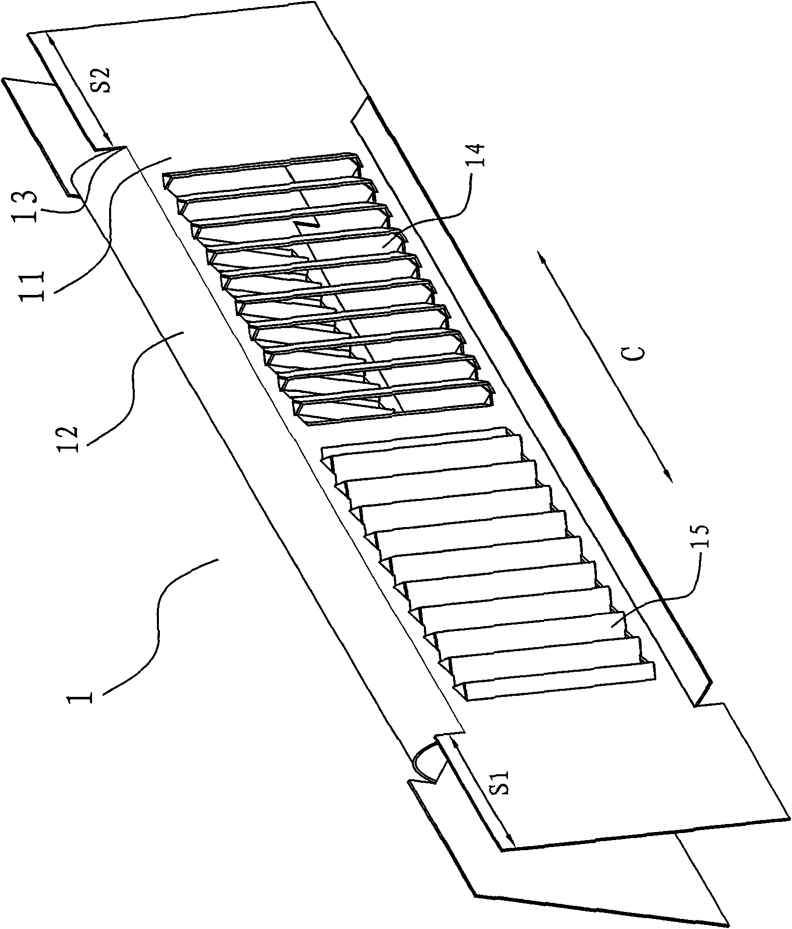
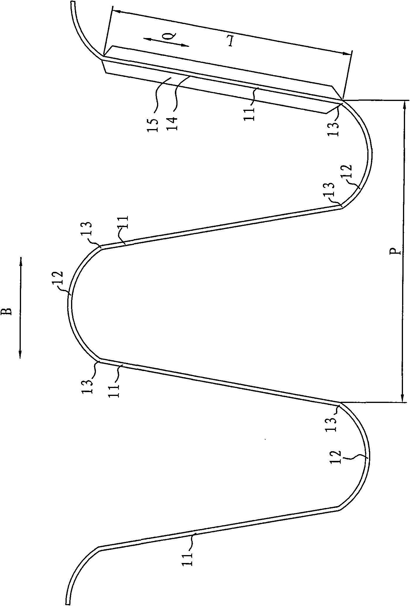
[0047] Such as image 3 As shown, the fin 1 according to the embodiment of the present invention is generally corrugated, and includes a straight section 11 and an arc section 12. The fin 1, wherein the arc segment 12 constitutes the crest and trough of the fin.

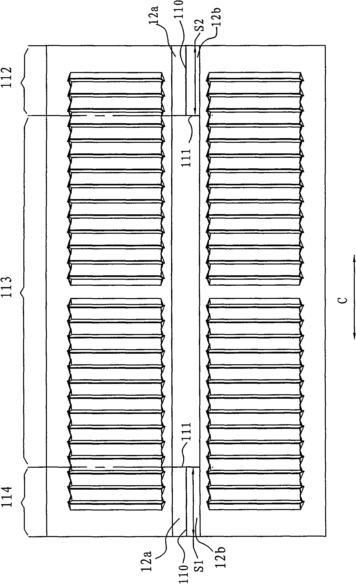
[0048] Such as figure 1 and 2 As shown, the fin 1 is divided in the transverse direction C into a first end portion 112 , a second end portion 114 , and...


PUM


Abstract

The invention provides a fin which is generally of a wave shape and comprises straight sections and arc sections, wherein the straight sections and the arc sections are sequentially connected so as to ensure that the arc sections form wave crests and wave troughs. The fin is divided into a first end part, a second end part and a middle part which is positioned between the first end part and the second end part along the transverse direction, wherein each arc section for at least forming the wave troughs in the first end part is separated from corresponding the arc section in the middle part through longitudinal cutting seams, and the arc top of each arc section for at least forming the wave troughs in the first end part is provided with transverse cutting seams along the transverse direction so as to ensure that each section for at least forming the wave troughs in the first end part is divided into a straight first part and a straight second part. The fin has good draining performance and reduces the gathering of condensed water. The invention also provides a heat exchanger with the fin.

Description

technical field [0001] The invention relates to a fin and a heat exchanger with the fin, in particular to a fin capable of improving the performance of removing condensed water and a microchannel heat exchanger with the fin. Background technique [0002] When the parallel flow heat exchanger is used as an evaporator or heat pump heat exchanger, for example, condensed water will be generated on the surface. In order to improve the performance of the heat exchanger to remove condensed water, the parallel flow heat exchanger usually adopts horizontal headers and flat tubes Install vertically between headers. [0003] For example, if Figure 10 and 11 A conventional parallel flow heat exchanger shown, Figure 10 is a schematic diagram of a conventional heat exchanger, Figure 11 yes Figure 10 The enlarged view of part G' in the figure, in order to improve the performance of removing condensed water, the headers 3a' and 3b' are arranged horizontally and parallel to each other ...

Claims


Application Information

Patent Timeline
Patent Type & Authority Applications(China)
IPC IPC(8): F28F3/02F28F3/04F28D1/053
CPCF28F1/128F28F17/005
Inventor 蒋建龙黄宁杰
Owner SANHUA(HANGZHOU) MICRO CHANNEL HEAT EXCHANGER CO LTD
Why Eureka
Try Eureka