Control device of electrically adjusted antenna
A technology for electronically adjustable antennas and control devices, applied to antennas, electrical components, etc., can solve the problems of inability to accurately obtain the relative moving position of the phase shifter after adjustment, damage to the phase shifter, and inability to eliminate the position error of the phase shifter, etc., to achieve Simple structure, eliminate position error, easy to use
- Summary
- Abstract
- Description
- Claims
- Application Information
AI Technical Summary
Problems solved by technology
Method used
Image
Examples
Embodiment 1
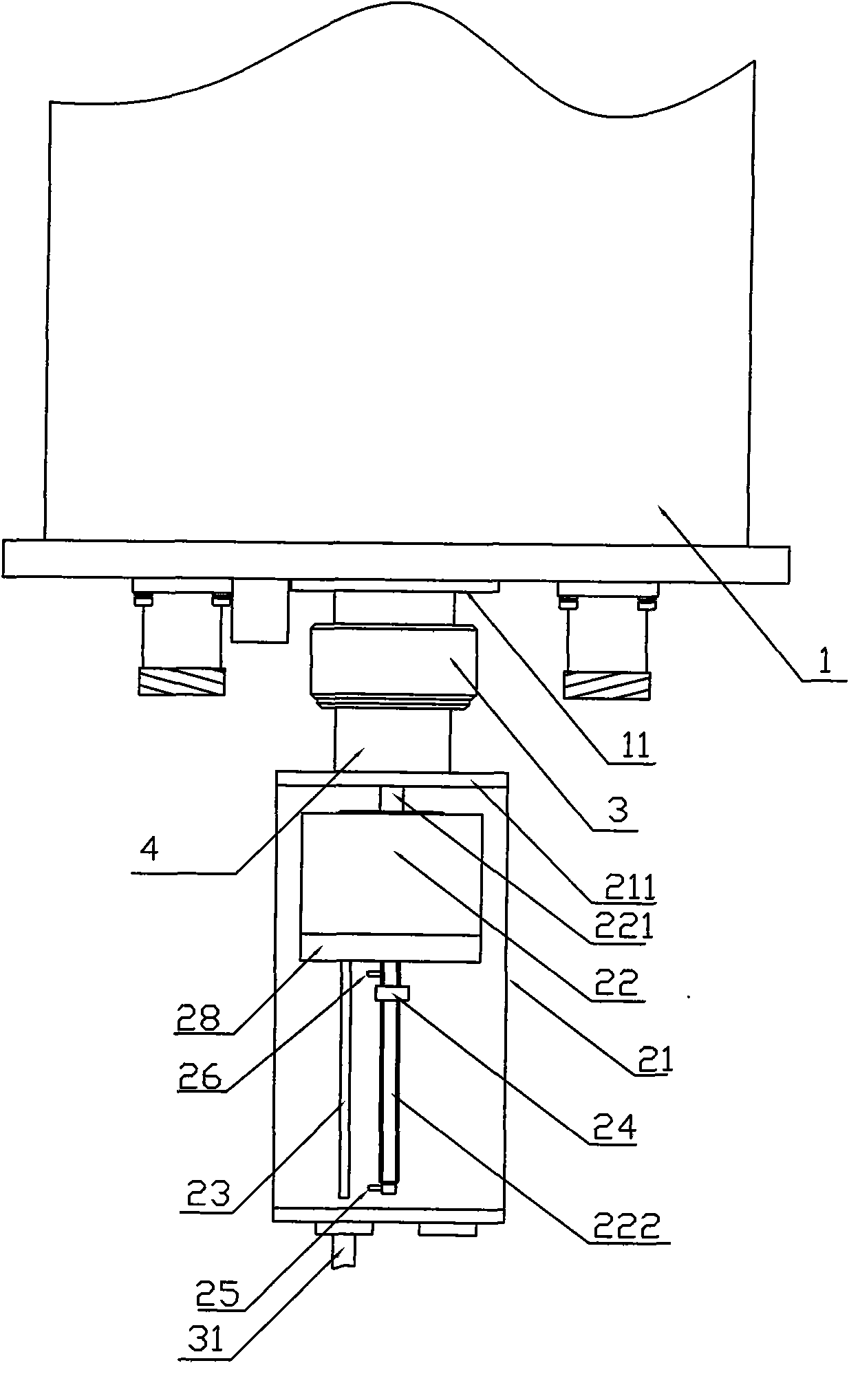
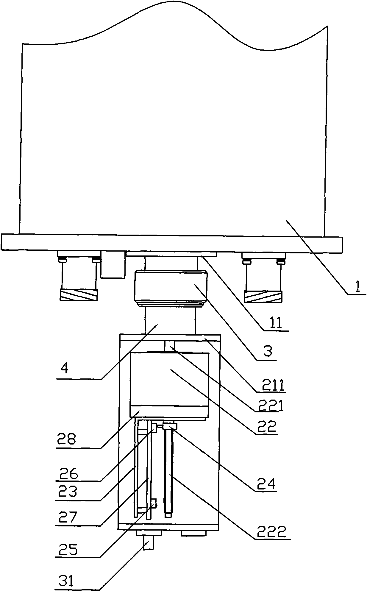
[0027] Such as figure 1 and 2 As shown, the electronically adjustable antenna 1 is located on the top of the mobile base station tower, and its downtilt angle can be adjusted by the rotating shaft of the phase shifter of the electrically adjustable antenna 1. The controller includes a housing 21, a motor 22 and an electric antenna downtilt angle control module 23 are arranged in the housing 21; the front end 221 of the rotating shaft of the motor 22 is connected with the rotating shaft seat 11 outside the electric antenna 1 through a connector 4 and a connecting nut 3, Wherein the connector 4 passes through the shell front cover 211 of the electronically adjustable antenna controller; the electronically adjustable antenna downtilt angle control module 23 is connected to the motor 22, and the electrically adjustable antenna downtilt angle control module 23 is used to output control signals to control the rotation axis of the motor and then control the rotation of the phase shi...
Embodiment 2
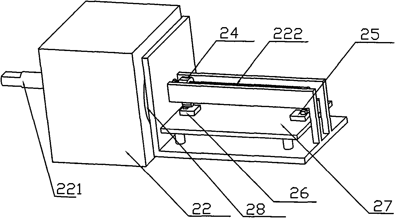
[0030] The difference from Embodiment 1 is that the two limit switches 25, 26 are respectively arranged on a limit plate 27 arranged parallel to the extension section of the rear end of the motor rotation shaft, see image 3 shown.
Embodiment 3
[0032] Different from Embodiment 1, the motor 22 is a motor with a deceleration mechanism, and the downtilt angle control module of the electric adjustable antenna is a printed circuit board, which is arranged in parallel with the extension section of the rear end of the motor rotating shaft, and the A strip-shaped slot is provided on the printed circuit board, and the slider can move linearly along the strip-shaped slot driven by the rotating shaft of the motor, while two limit switches 25, 26 are respectively arranged on the strip-shaped slot of the printed circuit board The two end edges of the bar groove, see Figure 4 shown.
PUM
 Abstract
Description
Claims
Application Information
 - R&D
- Intellectual Property
- Life Sciences
- Materials
- Tech Scout
- Unparalleled Data Quality
- Higher Quality Content
- 60% Fewer Hallucinations
Browse by: Latest US Patents, China's latest patents, Technical Efficacy Thesaurus, Application Domain, Technology Topic, Popular Technical Reports.
© 2025 PatSnap. All rights reserved.Legal|Privacy policy|Modern Slavery Act Transparency Statement|Sitemap|About US| Contact US: help@patsnap.com


