Numerical control relief grinding machine

A technology of gear shoveling machine and CNC machine tool, which is applied in the field of NC gear shoveling machine, and can solve problems such as low safety, poor positioning accuracy, and temperature influence

Pending Publication Date: 2020-04-03
东莞微航实业有限公司
View PDF0 Cites 2 Cited by
  • Summary
  • Abstract
  • Description
  • Claims
  • Application Information

AI Technical Summary

Problems solved by technology

[0003] The purpose of the present invention is to provide a digitally controlled gear shoveling machine to solve the problems existing in th...

Method used


Image

  • Numerical control relief grinding machine
  • Numerical control relief grinding machine
  • Numerical control relief grinding machine

Examples


Embodiment Construction

[0030] In order to make the purpose, technical solution and advantages of the present invention clearer, the technical solution of the present invention will be described in detail below. Apparently, the described embodiments are only some of the embodiments of the present invention, but not all of them. Based on the embodiments of the present invention, all other implementations obtained by persons of ordinary skill in the art without making creative efforts fall within the protection scope of the present invention.

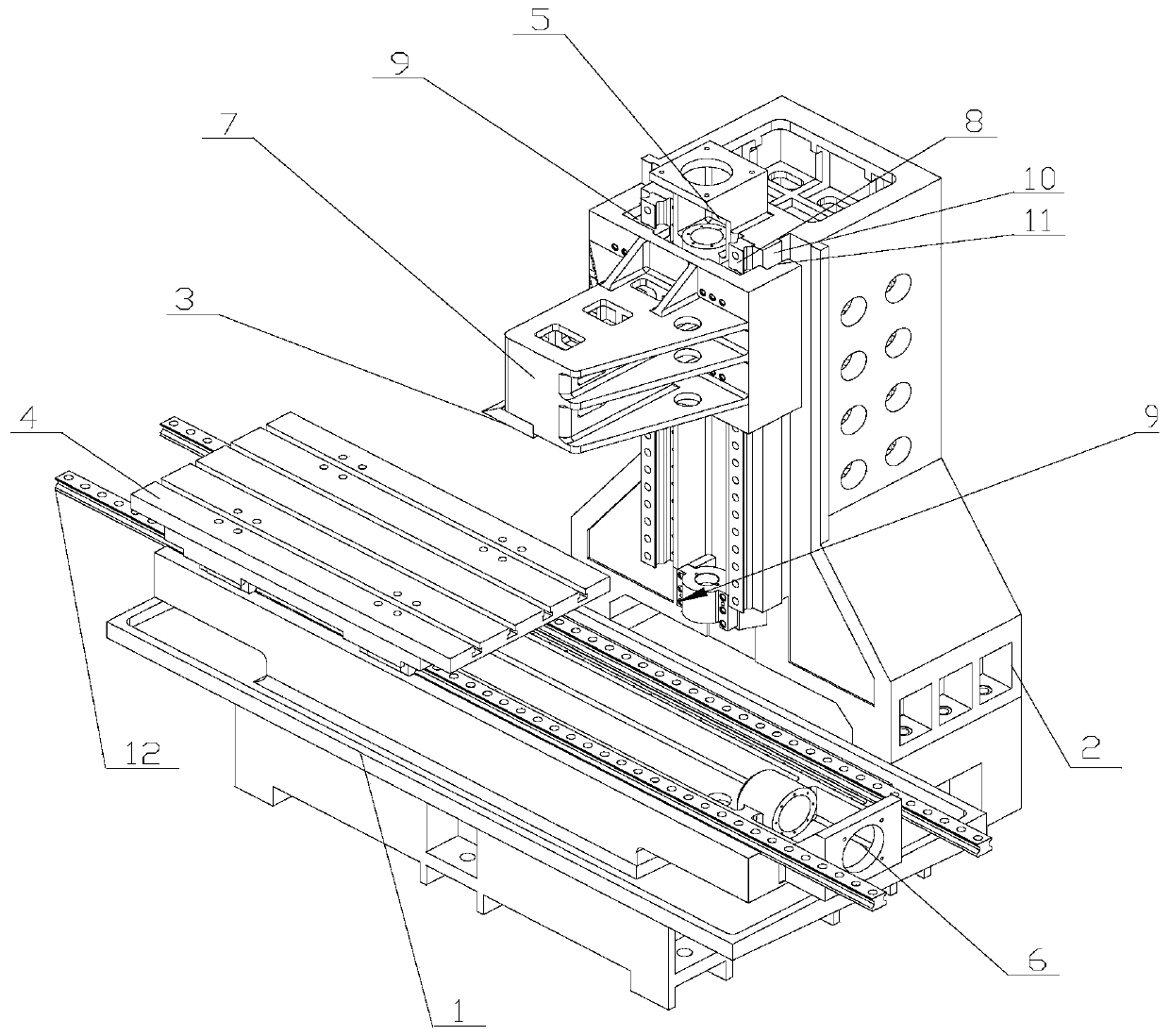
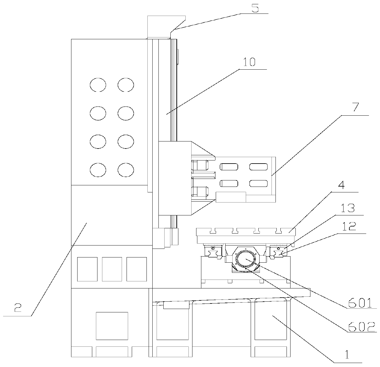
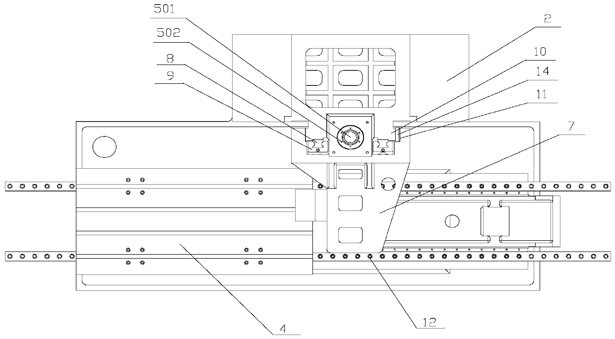
[0031] The purpose of this specific embodiment is to provide a digitally controlled gear shoveling machine to solve the problems of poor positioning accuracy, temperature influence, and low safety in the prior art of gear shoveling machines.

[0032]Hereinafter, an embodiment will be described with reference to the drawings. In addition, the examples shown below do not limit the content of the invention described in the claims in any way. In addition, all the ...


PUM


Abstract

The invention relates to the technical field of machining, and discloses a numerical control relief grinding machine. The numerical control relief grinding machine comprises a base, a stand column, arelieving mechanism, a first guide mechanism, a first power mechanism, a workbench, a second guide mechanism and a second power mechanism, wherein the relieving mechanism comprises a backed-off cutterand is connected to the stand column through the first guide mechanism, the guide direction of the first guide mechanism is the same as the height direction of the stand column, the first power mechanism comprises a first motor and a first transmission piece, the first transmission piece is connected with the relieving mechanism to drive the relieving mechanism to move, the guide direction of thesecond guide mechanism is the same as the length direction of the base, the workbench is connected to the base through the second guide mechanism, the second power mechanism comprises a second motorand a second transmission piece connected with the second motor, and the second transmission piece is connected with the relieving mechanism to drive the relieving mechanism to move. According to themachine, the problems that in the prior art, the relief grinding machine is driven by the hydraulic driving, so that positioning precision is poor, the temperature is influenced, the safety is not high and the like are solved.

Description

technical field [0001] The invention relates to the technical field of mechanical processing, and more specifically, relates to a numerically controlled gear-shoveling machine. Background technique [0002] Shoveling machining is to shovel up the surface of the workpiece and bend it upwards. The shoveling machine includes a base and a column. The guide mechanism on the column moves along the height direction of the column to adjust the distance between the column and the workbench, and the workbench moves along the length direction of the base through the guide mechanism set on the base to adjust the distance between the workpiece on the workbench and the shoveling mechanism , so that the shoveling mechanism can process the parts to be processed on the workbench. The shoveling machine in the prior art uses hydraulic drive to move the shoveling mechanism and the workbench, but the positioning of the hydraulic drive is inaccurate and prone to failure, and the hydraulic pressur...

Claims


Application Information

Patent Timeline
IPC IPC(8): B23D79/00B23Q1/56
CPCB23D79/00B23Q1/56
Inventor 陈云飞
Owner 东莞微航实业有限公司
Why Eureka
Try Eureka