Cylinder cover valve seat ring valve wire grinding and flapping machine

A valve seat ring and cylinder head technology, which is applied in the directions of grinding machine parts, grinding feed motion, grinding/polishing equipment, etc. Problems such as poor processing effect of seat ring finish

Pending Publication Date: 2020-01-03
ZHEJIANG NUOKEN MASCH TECH CO LTD
View PDF0 Cites 2 Cited by
  • Summary
  • Abstract
  • Description
  • Claims
  • Application Information

AI Technical Summary

Problems solved by technology

During the opening and closing process of the valve stem, it cooperates with the valve seat ring's valve line, so the airtightness of the fit between the valve seat ring valve line and the valve is very important. If there are burrs, it will affect the airtightness of the valve seat ring and the valve
The valve seat ring of the cylinder head in the prior art is usually not subjected to secondary grinding and beating after the processing is completed, or the valve seat ring is ground by manually holding a single valve grinding machine, the processing efficiency is low, and only grinding is performed. Poor machining effect on valve seat finish

Method used


Image

  • Cylinder cover valve seat ring valve wire grinding and flapping machine
  • Cylinder cover valve seat ring valve wire grinding and flapping machine
  • Cylinder cover valve seat ring valve wire grinding and flapping machine

Examples


Embodiment Construction

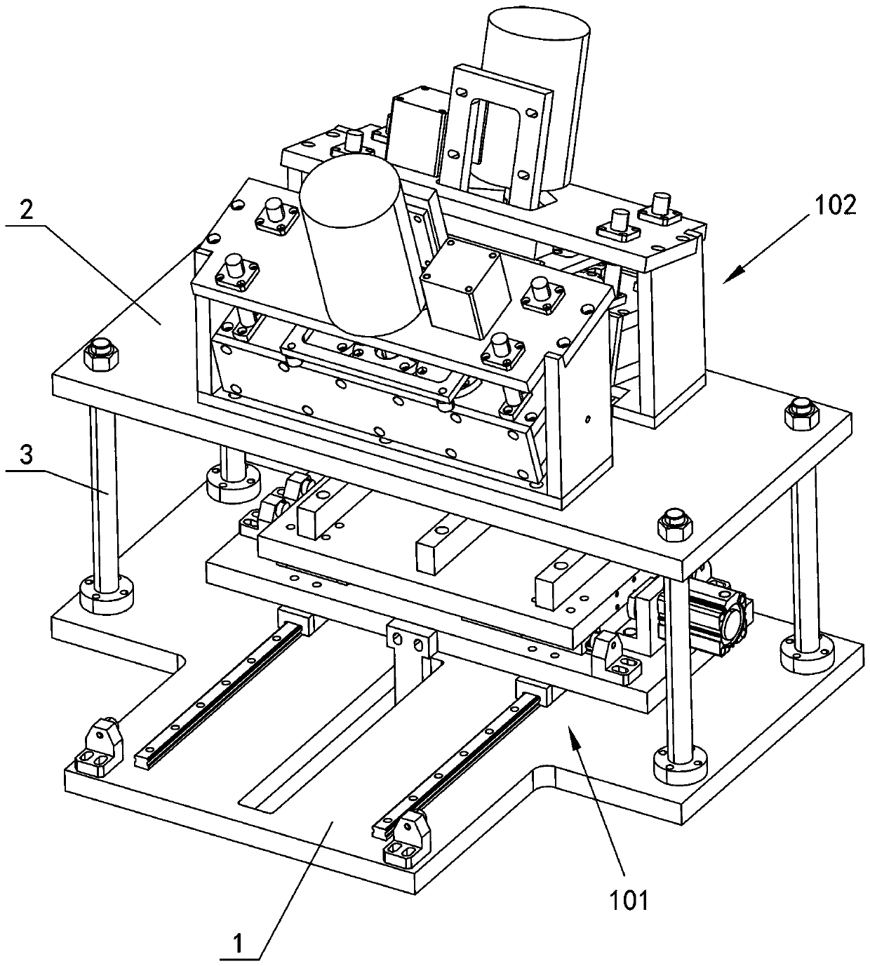
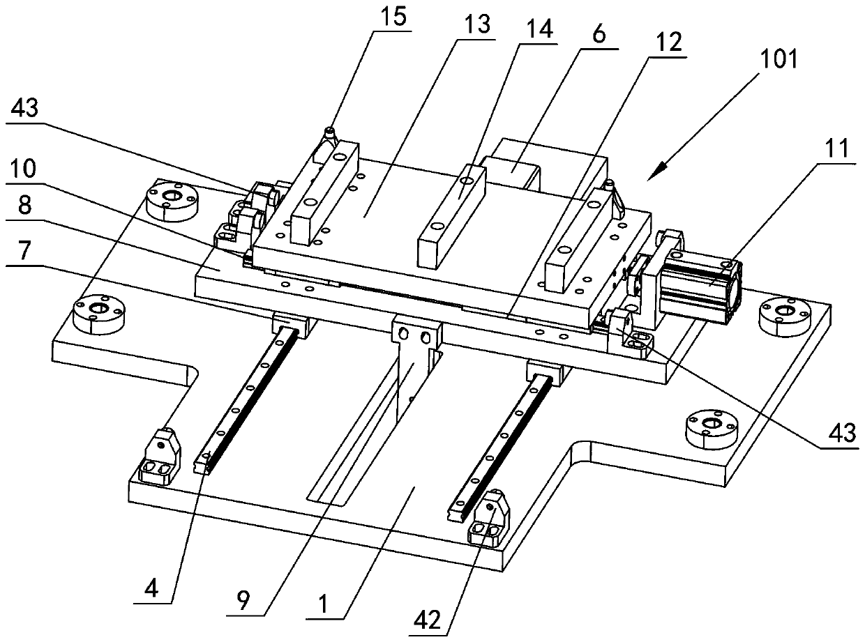
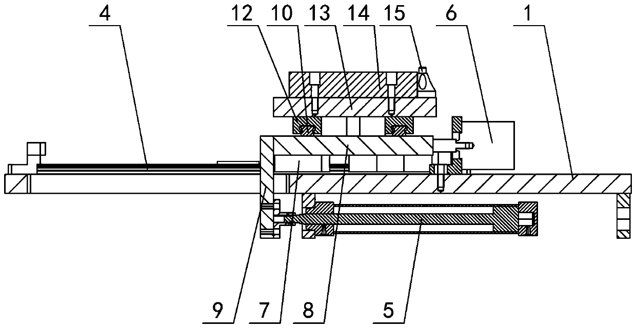
[0018] The invention relates to a cylinder head valve seat ring grinding and beating machine, such as figure 1 — Figure 11As shown, it includes a lower fixed plate 1 and an upper fixed plate 2, a support rod 3 is connected between the upper and lower fixed plates, a cylinder head positioning and moving device 101 is arranged on the lower fixed plate, and two groups of front and rear rotating lifting devices 102 are arranged on the upper fixed plate , the cylinder head positioning and moving device 101 includes front and rear slide rails 4, long distance front and rear movement cylinders 5 and short distance front and rear movement cylinders 6, the front and rear slide rails, long distance front and rear movement cylinders and short distance front and rear movement cylinders are connected with the lower fixed plate Fixed, the front and rear sliders 7 are set on the front and rear slide rails, and the front and rear slide plates 8 are set on the front and rear sliders. The pist...


PUM


Abstract

The invention provides a cylinder cover valve seat ring valve wire grinding and flapping machine. The cylinder cover valve seat ring valve wire grinding and flapping machine comprises a lower fixed plate and an upper fixed plate; supporting rods are connected between the upper fixed plate and the lower fixed plate; a cylinder cover locating movable device is arranged on the lower fixed plate; twogroups of rotary lifting devices in a front and back manner are arranged on the upper fixed plate; the rotary lifting devices comprise brackets; mounting plates are arranged on the brackets; reciprocating air cylinders are arranged on the mounting plates; the reciprocating air cylinders are connected with gear boxes; fixed frames are arranged on the gear boxes; motors are arranged on the fixed frames; driving gears and synchronizing gears are arranged in the gear boxes; synchronizing gears are connected with rotating shafts; the lower ends of the rotating shafts penetrate through the gear boxes; outer sleeves sleeve the lower ends of the rotating shafts; bases are arranged at the lower parts of the outer sleeves; oblique bumps are arranged on the bases; oblique guide surfaces and straightsurfaces are arranged on the oblique bumps; slots and limiting grooves are formed in the lower ends of the rotating shafts; rotating rods are arranged in the slots; limiting pins and sliding pins arearranged on the outer walls of the rotating rods; springs are arranged at the parts, located at the upper parts of the limiting pins, of the outer walls of the rotating rods; the sliding pins of the rotating rods are in fit with the oblique guide surfaces of the oblique bumps; sucking discs are arranged at the lower ends of the rotating rods; and the lower ends of the sucking discs and valve rodsare sucked.

Description

technical field [0001] The invention relates to a valve seat ring grinding and beating machine for a cylinder head, belonging to the field of cylinder head processing equipment. Background technique [0002] The valve seat and valve stem in the engine cylinder head are one of the key components that affect the reliability and safety of the engine. They are mainly used to start and close the intake and exhaust passages during the working process of the engine, and to control the fuel mixture or air. entry and discharge of exhaust gas. During the opening and closing process of the valve stem, it cooperates with the valve line of the valve seat, so the airtightness of the fit between the valve seat line and the valve is very important. Burrs will affect the airtightness of the valve seat ring and the valve. The valve seat ring of the cylinder head in the prior art is usually not subjected to secondary grinding and beating after the processing is completed, or the valve seat r...

Claims


Application Information

Patent Timeline
Patent Type & Authority Applications(China)
IPC IPC(8): B23P23/00B24B41/00B23Q7/00
CPCB23P23/00B23Q7/00B24B41/00B24B41/005
Inventor 杨程日
Owner ZHEJIANG NUOKEN MASCH TECH CO LTD
Why Eureka
Try Eureka