
Common pilot frequency hopping method in LTE system

A long-term evolution system and common pilot technology, which is applied in the field of the long-term evolution system of the 3rd Generation Partnership Project, can solve problems such as common pilot collisions, and achieve the effect of simplifying the planning process

Inactive Publication Date: 2010-01-06
ZTE CORP
View PDF0 Cites 8 Cited by
  • Summary
  • Abstract
  • Description
  • Claims
  • Application Information

AI Technical Summary

Problems solved by technology

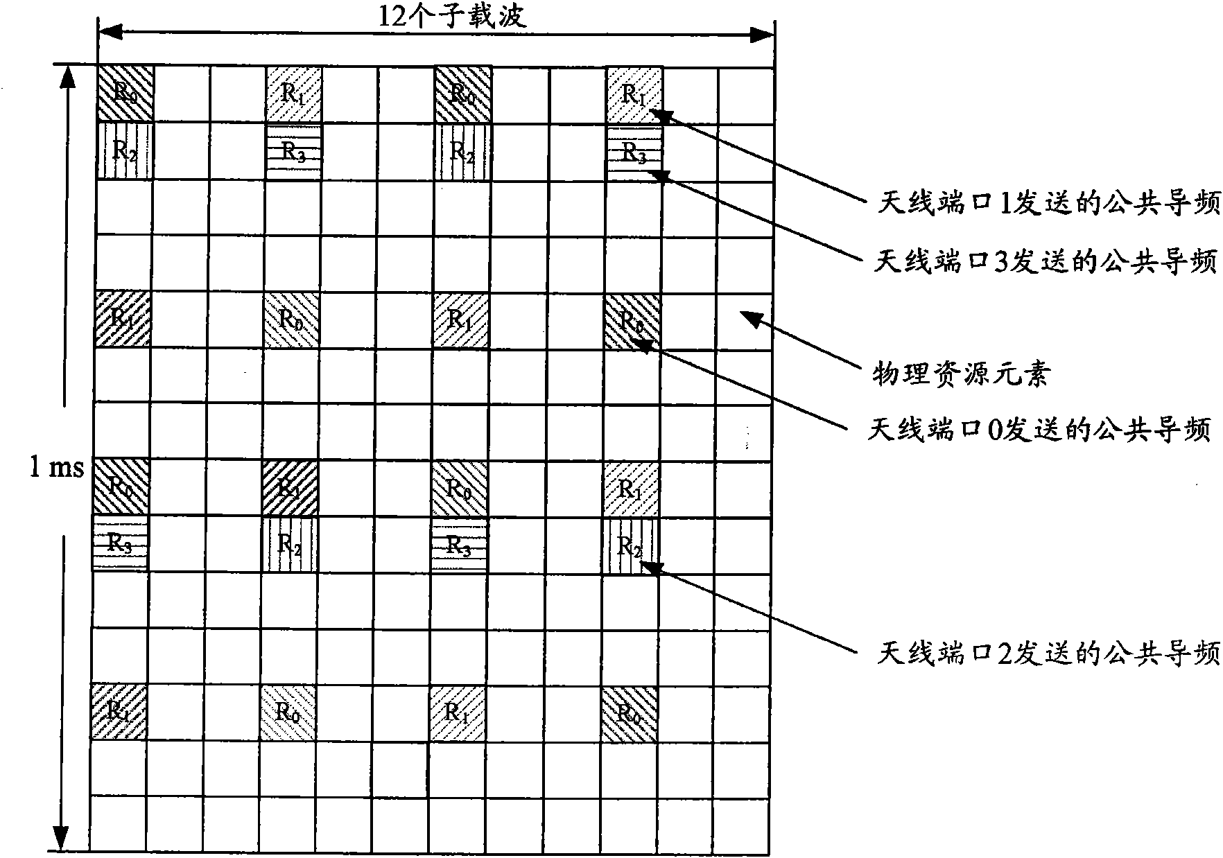
[0024] However, this common pilot frequency hopping method will lead to the collision of common pilots on different antenna ports of adjacent cells

Method used


Image

  • Common pilot frequency hopping method in LTE system
  • Common pilot frequency hopping method in LTE system
  • Common pilot frequency hopping method in LTE system

Examples


Embodiment Construction

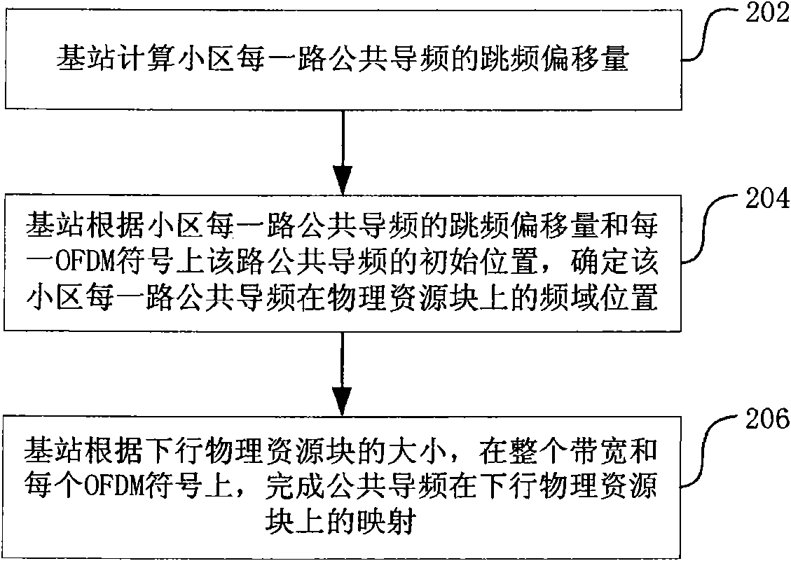
[0039] In view of this, an embodiment of the present invention provides a frequency hopping method for downlink common pilots in an LTE system.

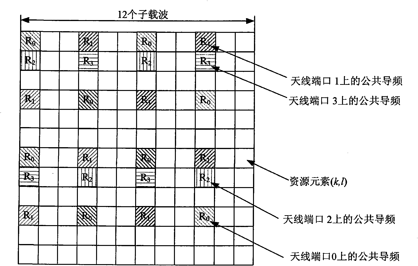
[0040] The common pilot frequency hopping offset v used in this embodiment shift It is determined according to the following principles: first, ensure that the common pilots of adjacent cells are not sent at the same position in the frequency domain; second, ensure that common pilots of different antenna ports of adjacent cells will not collide. For this reason, this embodiment sets the frequency hopping offset of the downlink common pilot as v shift = N ID cell mod 3 , That is, frequency hopping is performed modulo 3. At this time, the frequency hopping offset can only be 0, 1, or 2. The offsets of adjacent cells can be different through cell ID planning. Refer to figure 1 and figure 2 It can be seen t...


PUM


Abstract

The invention relates to a common pilot frequency hopping method in an LTE system, including that frequency hopping offset is limited to be within the minimum of resource units located between two common pilot frequencies on the same orthogonal frequency divided multiplex OFDM symbol when a base station is in frequency hopping on each downlink common pilot frequency of a cell. The frequency hopping method of the invention can avoid collision of common pilot frequencies on different antenna ports of adjacent cells, so that channel estimation of the common pilot frequency obtains more stable frequency hopping gain.

Description

technical field [0001] The present invention relates to the 3rd Generation Partnership Project Long term evolution (3rd Generation Partnership Project Long term evolution, referred to as 3GPP LTE) system, in particular to a common pilot frequency hopping method in the LTE system. Background technique [0002] In the LTE system, common pilots are used for channel estimation of data channels in multi-antenna modes such as PDCCH (Physical Control Channel), PBCH (Physical Broadcast Channel) and precoding. Common pilots are used on antenna ports 0, 1, 2, 3 send. [0003] The 3GPP (3rd Generation partnership project, third generation mobile communication partnership project) TS36.211v8.3.0 determines the frequency hopping method of the common pilot. It is stipulated in the text: [0004] a k , l ( p ) = r ...

Claims


Application Information

Patent Timeline
IPC IPC(8): H04B7/26H04B1/713
CPCH04B2001/7154H04B1/715H04J11/0023
Inventor 姜静孙云锋于辉夏树强张峻峰胡留军
Owner ZTE CORP
Learn More