Oil-lubricated kinematic module connecting system, mainly the transmission or bearing modules of industrial robot; method of kinematic module lubrication

A technology for industrial robots and motion modules, applied in manipulators, manufacturing tools, etc., can solve the problems of not restricting the freedom of robot motion, reducing dynamic characteristics, unsuitable for robot transmission or bearing modules, etc., to reduce environmental burden, increase life and Reliability and lubricity improvement effect

Pending Publication Date: 2020-09-25
易洛博特公司
View PDF10 Cites 0 Cited by
  • Summary
  • Abstract
  • Description
  • Claims
  • Application Information

AI Technical Summary

Problems solved by technology

[0007] Lubrication and friction diagnostic solutions are also known in the field of large rotating parts such as steam turbines; however, all such known methods are not suitable for robot transmission or bearing modules, because the technical solution of the robot cannot limit the movement of the robot degrees of freedom or reduce its dynamics

Method used


Image

  • Oil-lubricated kinematic module connecting system, mainly the transmission or bearing modules of industrial robot; method of kinematic module lubrication
  • Oil-lubricated kinematic module connecting system, mainly the transmission or bearing modules of industrial robot; method of kinematic module lubrication
  • Oil-lubricated kinematic module connecting system, mainly the transmission or bearing modules of industrial robot; method of kinematic module lubrication

Examples


example 1

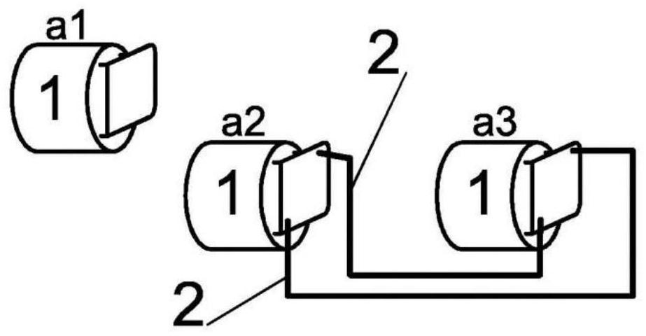
[0045] In this example and based on figure 1 , the manipulator has four revolving joints mounted and moved through a motion module 1 in the form of a bearing reducer. Three of these motion modules 1 , considered the most dynamically utilized, cooperate with gearboxes through pipe and hose connections. The oil circulation between the movement modules 1 is provided by the movement of the planetary gears of the reducer itself; there is no need to connect the pump 3 .

example 2

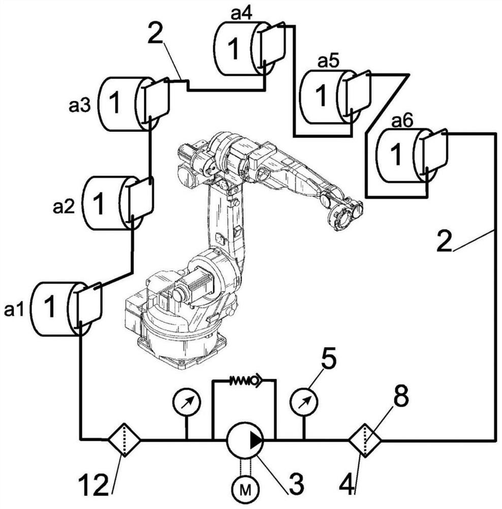
[0047] In this example, based on figure 2 , the oil-filled interconnection of all six motion modules 1 of the industrial robot. The connection is a simple series circulation loop where the oil flows from the highest motion module 1 to the next motion module 1 . From the last lowest movement module 1 , the oil is pumped to the highest movement module 1 via the suction filter 12 and via the filter device 4 by the pump 3 . To protect the pump 3 and its motor, the system is equipped with a bypass valve and two pressure sensors connected before and after the pump 3 .

[0048] The box of the lowest motion module 1 is used as the oil box for the whole system. The motion module is designed for maximum static and dynamic loads as it carries all adjacent arms and joints.

example 3

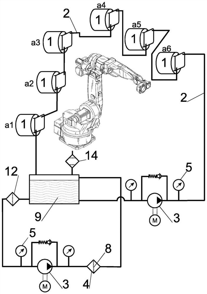
[0050] In this example, according to image 3 , the series connection of the previous example is supplemented by a separate filter circuit comprising an oil tank 9 into which oil flows from the last movement module 1 . A pressure variation compensator 14 is connected to the oil reservoir 9 ; this compensator is in the form of a breather filter in this example. The oil reservoir 9 is connected via the pump 3 to the branch circuit with the movement module 1; it is also connected to the filter device circuit 4, which consists of a replaceable filter element 8, the pump 3 with the motor, the bypass valve and a pair of pressure sensors . The suction filter 12 serves as protection against the introduction of coarse impurities into the pump 3 .


PUM


Abstract

The oil content of at least two kinematic modules (1) in different axes of the industrial robot is connected by the oil line (2) to the closed circuit of the oil between interconnected kinematic modules (1). In preferred arrangement, the system includes the pump (3) engaged in pushing the oil in the upper-mounted kinematic module (1) and also the filtration device (4) for filtering the oil in thecirculating circuit or in a separate circuit with the oil tank (9). The system may also include at least one diagnostic element (5), for example an oil temperature sensor or an oil pressure sensor oran oil pollution sensor connected to the evaluation unit (6). The evaluation unit (6) can be interconnected with the industrial robot control system, whereby the oil economy is controlled and planneddepending on the actual load of the individual kinematic modules (1). By this arrangement, you can achieve the condition in which the oil from the kinematic module (1) circulates in shared circulationwith the oil from another kinematic module (1), whereas the oil gets purified through the filter device (4) by using the pump (3).

Description

technical field [0001] The present invention relates to an interconnection system of modules, such as modules, which have their own oil fill to lubricate moving parts, mainly of transmission or bearing assemblies. Advantageously, this solution can be applied in the case of industrial robots and manipulators. The object of the invention is also a method of lubricating movement modules, mainly industrial robots. Background technique [0002] Robots, manipulators and similar devices with movable joints and arms are equipped with bearings and transmission modules that provide the reciprocating rotational movement of each single part of the device. There are also bearing reducers, which function as rolling bearing housings in one housing and also as gearboxes. The modules have their own oil-lubricated fill. Although the individual modules have been designed to achieve the same service life or the same working life according to the prescribed maintenance actions, the actual loa...

Claims


Application Information

Patent Timeline
Patent Type & Authority Applications(China)
IPC IPC(8): B25J19/00
Inventor L·依莱克欧
Owner 易洛博特公司
Why Eureka
Try Eureka