Carton box cleaner

A technology for cleaning machines and cartons, applied in the direction of cleaning hollow objects, cleaning methods and utensils, chemical instruments and methods, etc., can solve problems affecting food hygiene, food pollution, etc., and achieve the effects of improving hygiene quality, easy operation, and easy control

Inactive Publication Date: 2010-01-13
DALIAN RAPIDER WOOD PRODS
View PDF0 Cites 5 Cited by
  • Summary
  • Abstract
  • Description
  • Claims
  • Application Information

AI Technical Summary

Problems solved by technology

[0002] Cartons are widely used to hold food. After the carton is made, there will be a certain am...

Method used


Image

  • Carton box cleaner
  • Carton box cleaner

Examples


Embodiment Construction

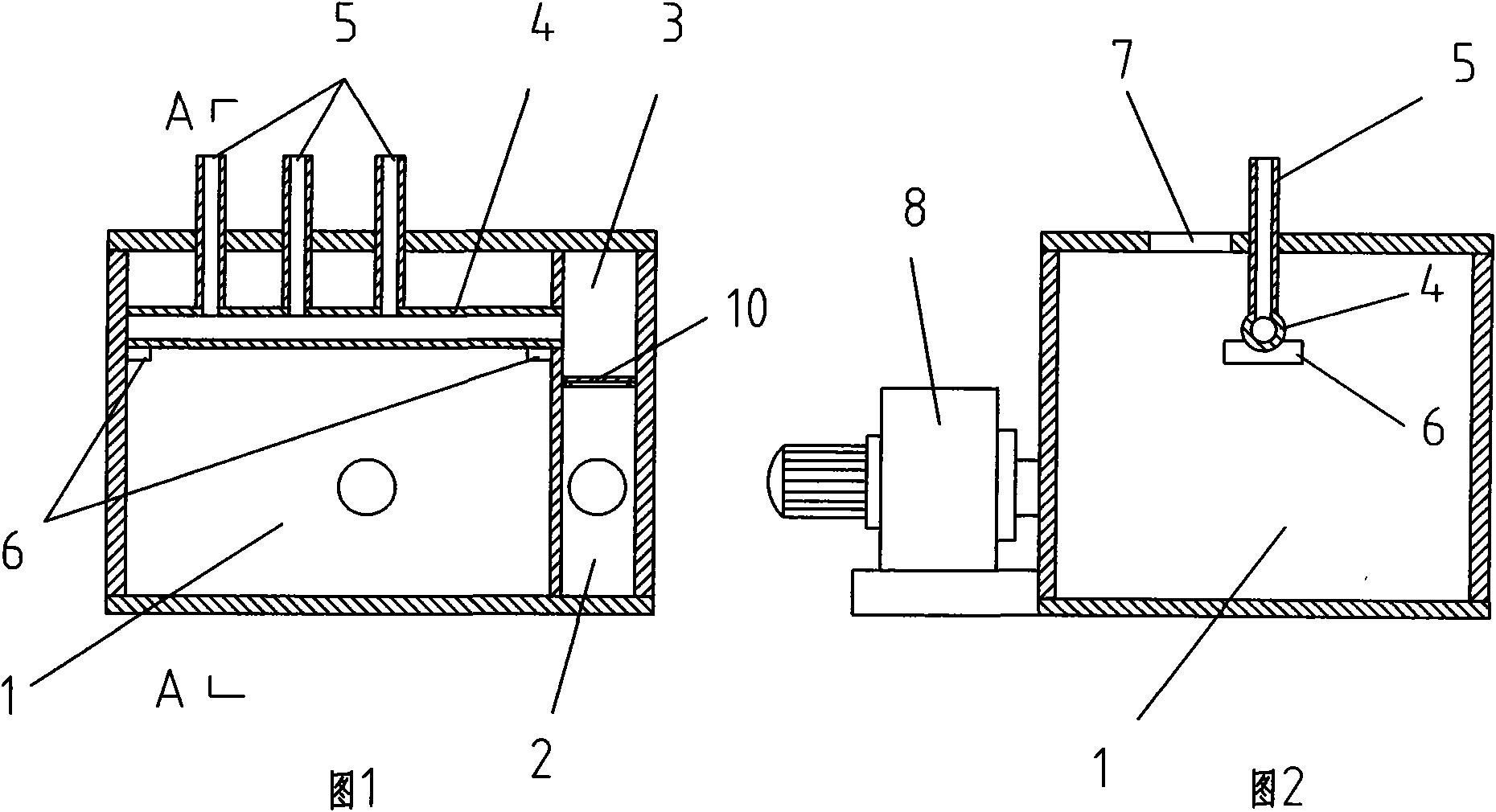
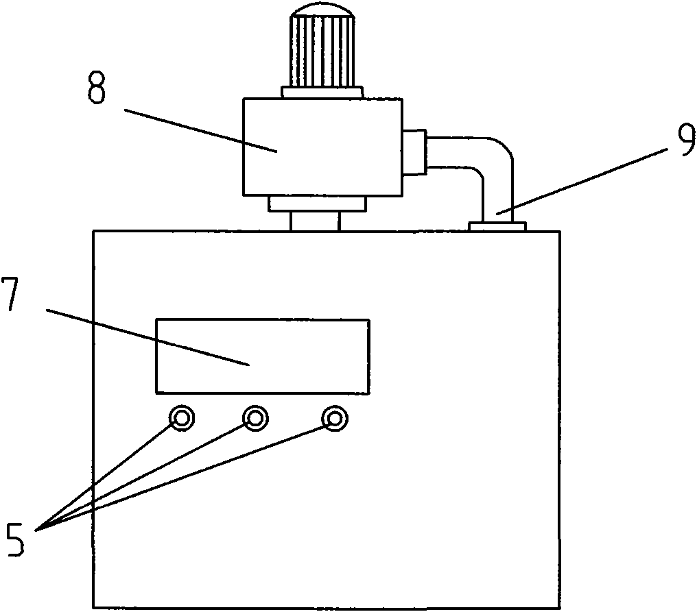
[0010] Such as figure 1 , 2 , 3 shows: 1 is the suction chamber, the exhaust chamber 2 is arranged on the side of the suction chamber 1, and the filter gas chamber 3 is arranged above the exhaust chamber 2, and each chamber is welded by metal plate or fixedly connected by screws form. A gas filter 10 is installed between the exhaust cavity 2 and the filtered gas cavity 3, and the gas filter 10 is a filter screen or a filter cloth, and is fixedly installed through a frame. A fan 8 is fixedly installed on the side of the suction chamber 1 , the inlet of the fan 8 communicates with the suction chamber 1 , and the outlet 9 of the fan 8 communicates with the exhaust chamber 2 . An exhaust pipe 4 is fixed laterally through the support platform 6 inside the suction chamber 1 , and one end of the exhaust pipe 4 communicates with the filtered gas chamber 3 . The exhaust port 5 connected with the exhaust pipe 4 is located above the outside of the suction chamber 1 . An air intake 7 ...


PUM


Abstract

The invention discloses a carton box cleaner which is mainly used for cleaning dust on the inner side of a carton box for containing food. The carton box cleaner comprises an air intake cavity (1); the inlet of a fan (8) is communicated with the air intake cavity (1), and the outlet (9) of the fan (8) is communicated with an exhausting cavity (2); an air filtering piece (10) is arranged between the exhausting cavity (2) and an air filtering cavity (3), and an exhausting pipe (4) is communicated with the air filtering cavity (3) and is connected with an exhausting port (5); the periphery of the exhausting port (5) is communicated with the air intake cavity (1). The invention has simple integral structure, easy operation, easy control and favourable dust removing effect on the inner side of the carton box and improves the hygienic quality of the carton box.

Description

technical field [0001] The invention relates to a carton cleaning machine, which is mainly used for cleaning the dust inside the carton containing food. Background technique [0002] Cartons are widely used to hold food. After the carton is made, there will be a certain amount of dust or other tiny particles inside, which may pollute the loaded food and affect food hygiene. Contents of the invention [0003] The purpose of the present invention is to provide a carton cleaning machine with simple overall structure, easy operation and good dust removal effect, which is used for cleaning the finished cartons. [0004] The carton cleaning machine of the present invention comprises an air suction chamber 1, the inlet of the fan 8 communicates with the air suction chamber 1, the outlet 9 of the fan 8 communicates with the exhaust chamber 2, and an exhaust chamber 2 and the filtered air chamber 3 are provided There is a gas filter 10, an exhaust pipe 4 is connected with the filt...

Claims


Application Information

Patent Timeline
IPC IPC(8): B08B9/20B08B9/34
Inventor 刘民田
Owner DALIAN RAPIDER WOOD PRODS
Why Eureka
Try Eureka