Cutter feeding device with controllable pressure angle

A technology of feeding device and pressure angle, which is applied in the direction of feeding device, manufacturing tools, metal processing machinery parts, etc., can solve the problems of poor processing surface quality, vibration, etc., and achieve the effect of compact structure and reliable operation

Inactive Publication Date: 2010-01-13
刘荣进
View PDF0 Cites 0 Cited by
  • Summary
  • Abstract
  • Description
  • Claims
  • Application Information

AI Technical Summary

Problems solved by technology

Climb milling causes vibration and poorer surface quality

Method used


Image

  • Cutter feeding device with controllable pressure angle
  • Cutter feeding device with controllable pressure angle

Examples


Embodiment Construction

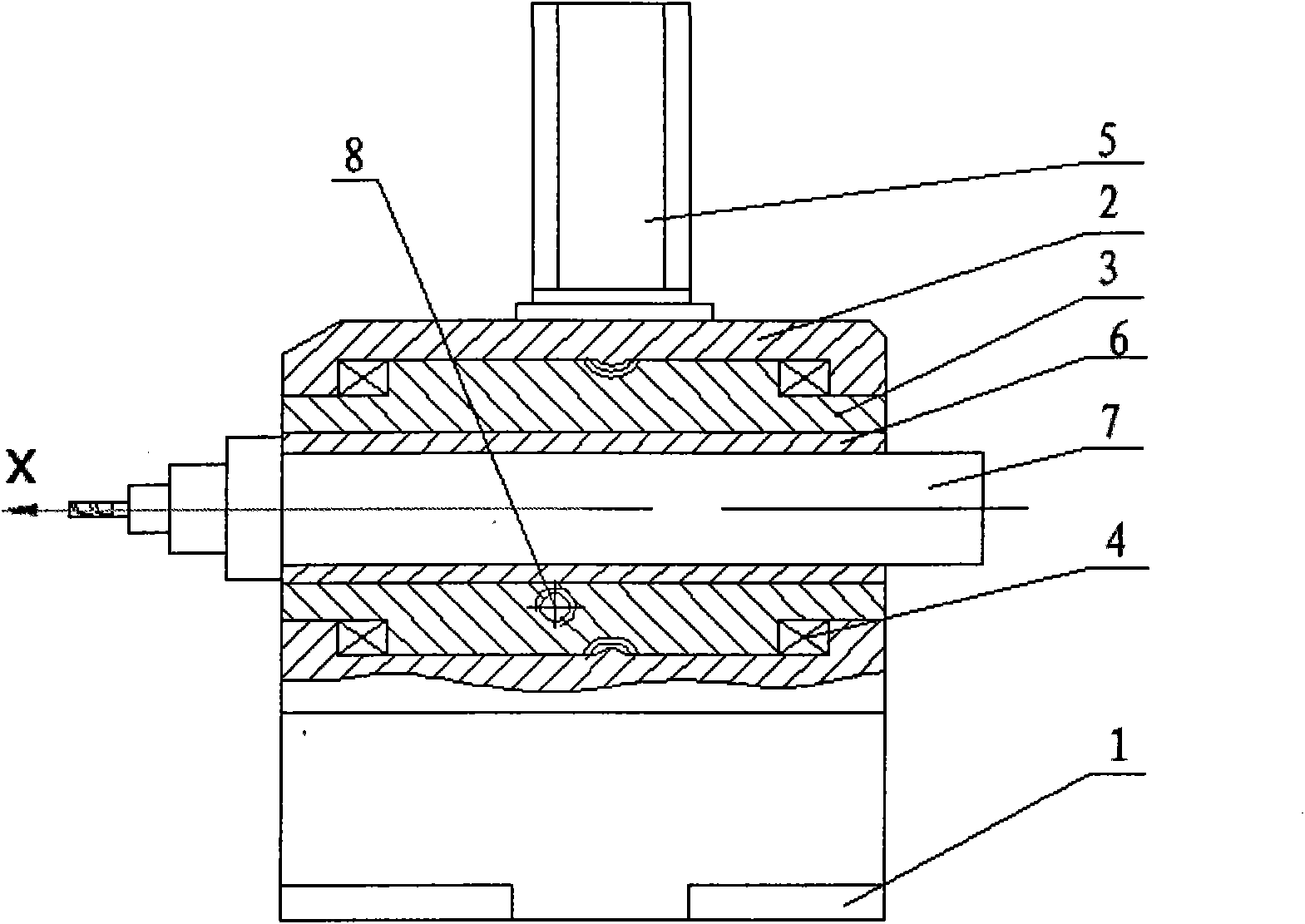
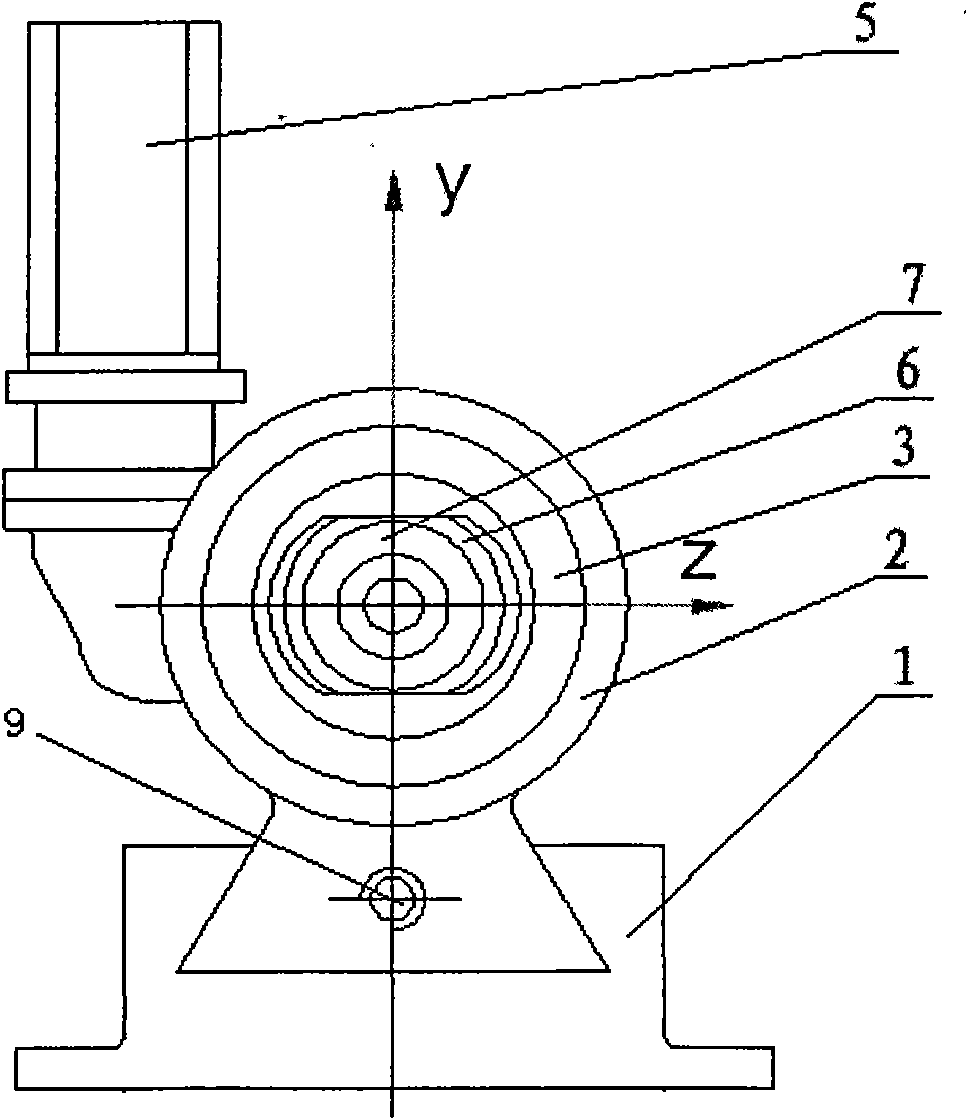
[0012] Referring to the accompanying drawings, a tool feeding device with controllable pressure angle includes a base 1 on which a housing 2 with a dovetail groove is slidably installed, and a main screw 9 passes through the housing 2, and the main screw 9 passes through the housing 2. The screw 9 drives the casing 2 to move longitudinally, and the worm wheel 3 is installed in the casing 2 through the rotation of the bearing 4, and a vertical worm shaft is installed on one side of the casing 2 to mesh with the worm wheel 3, and a control motor 5 drives the worm shaft Adjust the pressure angle of the cutter; a slide block 6 that can slide horizontally is installed in the inner hole of the worm wheel 3, and a horizontal lead screw 8 passes through the worm wheel 3, and the two ends of the lead screw 8 are rotated and installed in the worm wheel 3, and the thread on the lead screw 8 Fitted with a nut, the nut can drive the slide block 6 to slide left and right, and the electric sp...


PUM


Abstract

The invention discloses a cutter feeding device with controllable pressure angle, which is characterized by comprising a base, wherein a shell with a dovetail groove is arranged on the base in a sliding mode, a worm wheel is rotatably arranged in the shell, one side of the shell is provided with a vertical worm shaft which is meshed with the worm wheel to drive, the worm shaft is driven by a control motor to regulate a pressure angle of a cutter, a slide block which can transversely slide is arranged in an inner hole of the worm wheel, a transverse screw rod passes through the worm wheel, both ends of the screw rod are rotatably arranged in the worm wheel, the screw rod and the slide block helically drive, and an electric main shaft with a cutter is arranged in the slide block. A cutter with a diameter which is smaller than a groove width is used for cutting a single edge, thus, the pressure angle can be controlled to ensure an outer normal of a cutting curved surface to pass through a center of the cross section of the cutter, and the cutter feeding device with controllable pressure angle not only has a width direction feeding function, but also has a groove depth feeding function.

Description

technical field [0001] The invention belongs to a cutting tool feeding device, which is a cutting tool feeding device with controllable pressure angle for machining space groove-shaped curved surface. Background technique [0002] When cutting groove-shaped space surfaces, the diameter of the milling cutter is equal to the groove width. When the groove width needs to be increased, a tool with a larger diameter must be replaced to process. Each machining process needs to change a cutting tool, which increases the auxiliary time of machining. At the same time, the groove surfaces on both sides of this processing method are cut at the same time. On both sides of the tool, one side is up milling and the other side is down milling. Climb milling causes vibration and poorer surface quality. Contents of the invention [0003] The purpose of the present invention is to provide a tool feeding device with controllable pressure angle, which can realize unilateral cutting with a too...

Claims


Application Information

Patent Timeline
Patent Type & Authority Applications(China)
IPC IPC(8): B23Q5/32
Inventor 刘荣进林治金
Owner 刘荣进
Why Eureka
Try Eureka