Pneumatic oil pump

A pneumatic oil pump and oil pump technology, applied in the field of pneumatic oil pump and power unit of hydraulic system, can solve the problems of hydraulic oil leakage, large pressure loss, pipeline damage, etc., and achieve the effect of convenient adjustment, convenient use and compact structure

Active Publication Date: 2011-07-20
WUHU HONGJIN MACHINE TOOL
View PDF0 Cites 0 Cited by
  • Summary
  • Abstract
  • Description
  • Claims
  • Application Information

AI Technical Summary

Problems solved by technology

[0003] However, in some occasions, it is not possible to provide power on site. First, it is restricted by safety protection and is not allowed to use electricity on site, such as explosive dust and gas environments; Power supply is provided at a considerable distance. At this time, the hydraulic system needs to set the actuator at the construction site, and set the hydraulic pump at a place far away from the construction site to connect the power supply, which requires a long hydraulic pipeline. The problem is: 1. The longer the hydraulic pipeline, the greater the pressure loss, which cannot meet the load requirements of the actuator; road damage

Method used


Image

  • Pneumatic oil pump
  • Pneumatic oil pump

Examples


Embodiment Construction

[0018] Referring to the accompanying drawings, through the description of the embodiments, the specific implementation of the present invention, such as the shape, structure, mutual position and connection relationship between the various parts, the function and working principle of each part, and the manufacturing process And the method of operation and use, etc., are described in further detail to help those skilled in the art have a more complete, accurate and in-depth understanding of the inventive concept and technical solutions of the present invention.

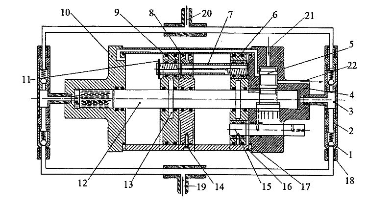
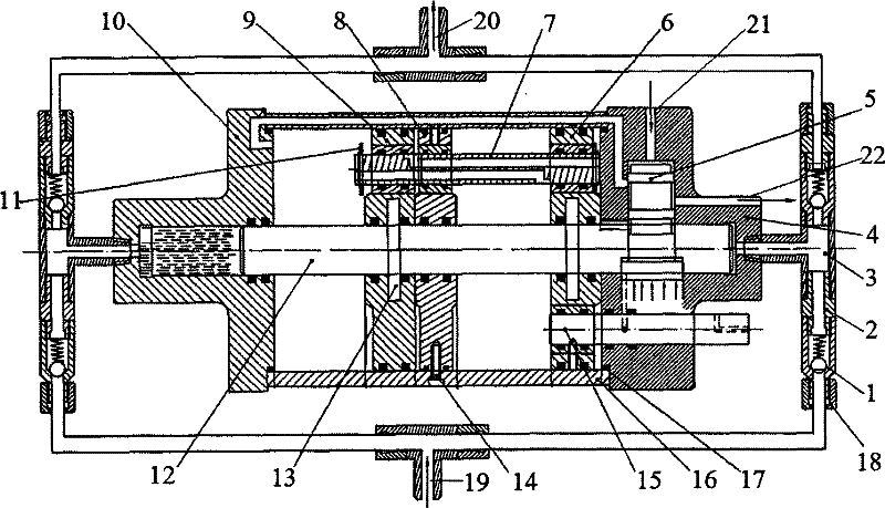
[0019] Such as figure 1 The structure of the present invention expressed, the present invention is a kind of pneumatic oil pump, comprises an oil inlet 19, an oil pressure port 20 and the oil pipe that connects these two oil ports.

[0020] In order to solve the problems existing in the current known technology described in the background technology section of this description and overcome its defects, and realize the i...


PUM


Abstract

The invention discloses a pneumatic oil pump which comprises an oil inlet, an oil compressing port and an oil pipe connecting with the oil inlet and the oil compressing port. A driving mechanism of the oil pump is a pneumatic device, i.e. the oil pipe between the oil inlet and the oil compressing port is divided into two hydraulic pipes which are communicated with each other end to end, and each hydraulic pipe is provided with two same check valves. The conducting direction of the check valves is from the oil inlet to the oil compressing port; a tee coupling is arranged between the two check valves on each hydraulic pipe; and the two tee couplings on the two pipes are connected with oil cavities at two ends of a pneumatic reciprocation cylinder. Adopting the technical scheme, the pneumatic oil pump utilizes pneumatic pressure to obtain continuous high-pressure hydraulic oil, can conveniently adjust the pressure to realize automatic pressure control of a system, does not need a power supply, realizes safe application, meets requirements of different construction places, is widely superior to various hydraulic transmission systems, and has compact structure and convenient use.

Description

technical field [0001] The invention belongs to the technical field of pneumatic and hydraulic transmission, and relates to a power device of a hydraulic system. More specifically, the invention relates to a pneumatic oil pump. Background technique [0002] In a hydraulic transmission system, a hydraulic pump needs to be installed, and the hydraulic pump should be as close as possible to the hydraulic actuator. The driving device of the hydraulic pump is an electric motor, which needs to be supplied with power. [0003] However, in some occasions, it is not possible to provide power on site. First, it is restricted by safety protection, and it is not allowed to use electricity on site, such as explosive dust and gas environments; The power supply is provided at a considerable distance. At this time, the hydraulic system needs to set the actuator at the construction site, and set the hydraulic pump at a place far away from the construction site to connect the power supply, w...

Claims


Application Information

Patent Timeline
Patent Type & Authority Patents(China)
IPC IPC(8): F04B9/123
Inventor 冯晓飞瞿国权
Owner WUHU HONGJIN MACHINE TOOL
Why Eureka
Try Eureka