Coating system and method for the series coating of workpieces

A coating and equipment technology, which is applied in the direction of surface coating liquid devices, coatings, spray booths, etc., can solve the problems of increased flow speed, etc., and achieve the effects of reducing costs, avoiding control costs, and avoiding structure costs

Inactive Publication Date: 2010-01-13
DUERR SYST GMBH
View PDF7 Cites 2 Cited by
  • Summary
  • Abstract
  • Description
  • Claims
  • Application Information

AI Technical Summary

Problems solved by technology

In addition, elevated mounted robots have the advantage that they interfere less with the airflow flowing from the roof down along the sides of the body into the chamber floor than robots situated next to the body on the bottom, which make it possible to Narrowing of the air passage in the immediate vicinity of the body, which can lead to an undesired increase in flow velocity

Method used


Image

  • Coating system and method for the series coating of workpieces
  • Coating system and method for the series coating of workpieces

Examples


Embodiment Construction

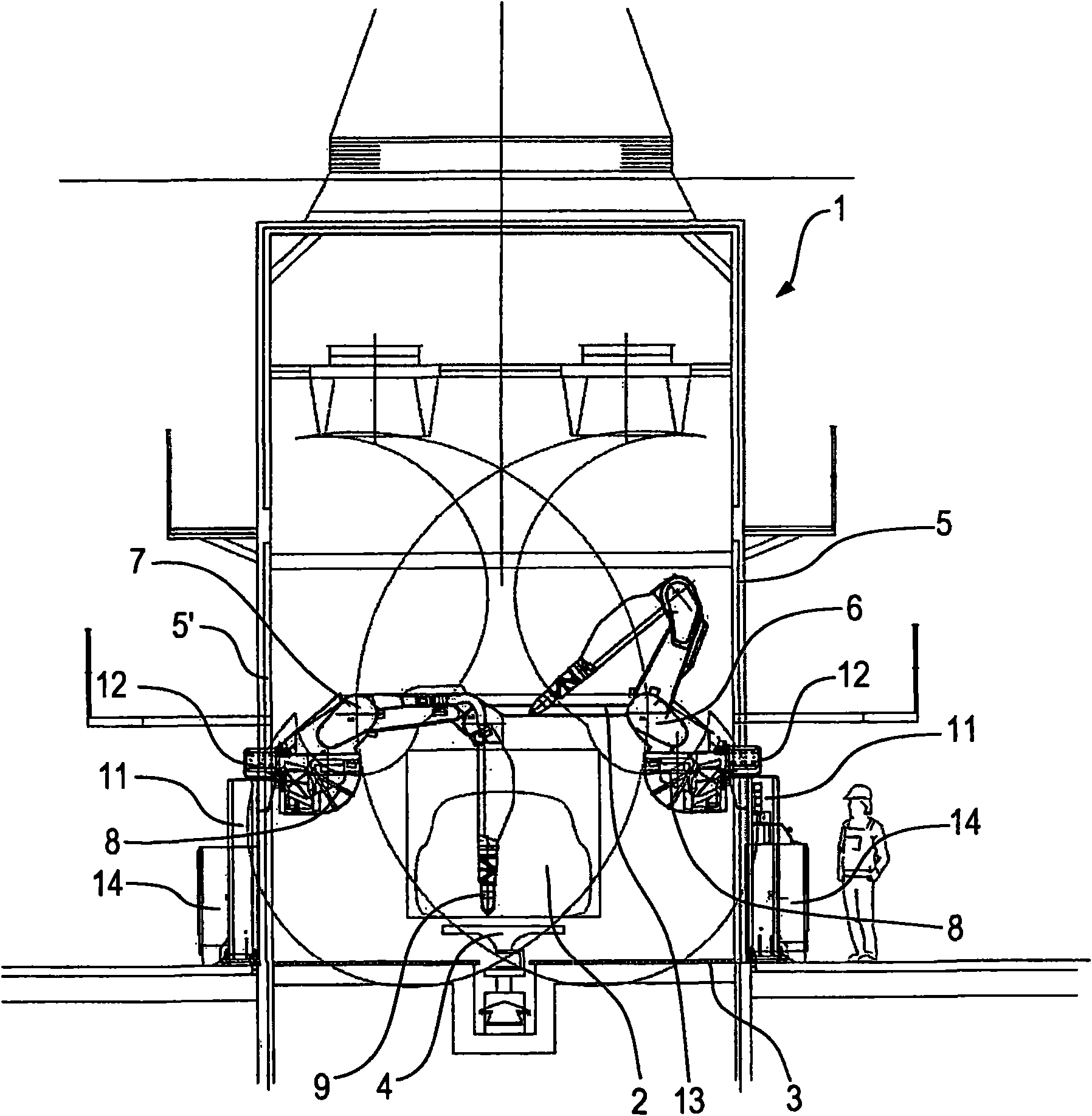
[0020] exist figure 1 In the shown spray booth 1 , paint is applied to a vehicle body 2 under the desired climatic conditions. The spray produced during painting is taken up by the air flowing vertically through the chamber and directed for flushing. The air supply device takes over the air supply function. Fresh air sucked in from the outside with a fan is filtered in multiple stages, heated, moistened, passed through the filter cover uniformly via the pressure chamber at a defined air settling velocity into the chamber and out through the grille bottom 3 . The bodywork can be conveyed by an underbody conveyor 4 through such a paint booth, which is known per se to the person skilled in the art (see eg DE 20313854).

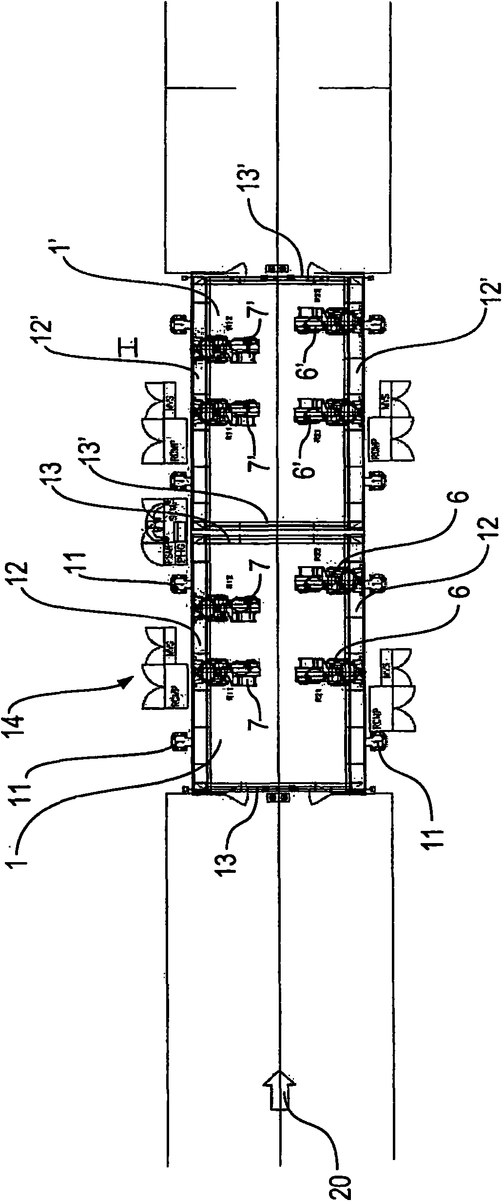
[0021] The painting of the body 2 is carried out by, for example, four or more painting robots arranged on the side walls 5 and 5' of said chamber 1, wherein in figure 1 Painting robots 6 and 7 can be seen in . These painting robots can likewise be in a mann...


PUM


Abstract

The series painting of vehicle bodies is carried out by painting robots (6, 7) which are mounted in the spray cabin (1) on a portal structure (11, 12, 13) so as to be stationary above the bodies (2).

Description

technical field [0001] The invention relates to a coating system for the batch coating of workpieces, in particular car bodies, as stated in the preamble of claim 1, and to a corresponding method. Background technique [0002] In contrast to fixed-position painting robots, which are typically used in practice for relatively small workpieces, painting robots in painting plants for vehicle bodies can usually be mounted on guide rails mounted on the side walls of the painting booth. The conveyor track moves linearly parallel to the body (entraining axis or "axis 7"). In most current installations, the car bodies are conveyed through the chamber during painting synchronously with the linear movement of the robot, but they can also be stationary here. [0003] Guide rails were especially in most early devices near the chamber bottom or beside the body (US 4 342 536, US 4 721 630, EP 0 084 523, EP 0 192 338, EP 0 216482, EP 1 277 521 etc.), while For various reasons, it may be e...

Claims


Application Information

Patent Timeline
Patent Type & Authority Applications(China)
IPC IPC(8): B05B13/04B05B15/12B05B16/00B05B16/40
CPCB05B13/0431B05B13/0452B05B15/1214B05B16/40B05B16/00B05B13/04
Inventor V·苏吉奥鲁茨兹J·克尔默齐
Owner DUERR SYST GMBH
Why Eureka
Try Eureka