Drive axle at least with one electric drive motor

A technology for driving axles and driving motors, applied in electric vehicles, motor vehicles, electric components, etc., can solve the problems of maintenance cost, unsealing, and affecting the efficiency of driving axles.

Active Publication Date: 2014-06-18
LINDE MATERIAL HANDLING
View PDF10 Cites 1 Cited by
  • Summary
  • Abstract
  • Description
  • Claims
  • Application Information

AI Technical Summary

Problems solved by technology

However, such grease-lubricated bearings in combination with wave seal rings for sealing the motor chamber against the transmission chamber cause frictional losses which affect the efficiency of the drive axle
A further disadvantage of the known drive axle is that with the failure of the bellows seal ring, for example, the bellows seal ring becomes leaky, resulting in damage to the bearing of the grease-lubricated bearing, resulting in a corresponding maintenance effort.

Method used


Image

  • Drive axle at least with one electric drive motor

Examples


Embodiment Construction

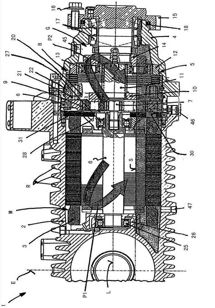
[0013] The drive axle 1 comprises a tubular axle housing 2 , which encloses a motor chamber M with its inner walls, in which an electric traction motor 3 is arranged. Travel motor 3 is preferably designed as an asynchronous electric motor. In the region of the motor chamber M, the outer wall of the axle housing 2 is provided with a ribbing R which forms corresponding cooling ribs.

[0014] A transmission housing 4 is flanged on the end of the wheel outer side of the axle housing 2, and the transmission housing surrounds a transmission chamber G with an inner wall, and the transmission 5 driven by the traveling motor 3 is arranged in the transmission compartment.

[0015] In the exemplary embodiment shown, the transmission 5 is designed as a two-stage planetary transmission, wherein the rotor shaft 6 of the travel motor 3 is drivingly connected to the sun gear 7 of the first planetary transmission stage. The ring gear 8 of the first planetary transmission stage is fixed to th...


PUM


Abstract

The drive axle (1) has liquid cooling system for drive motor (3) for lubrication of gear box (5) in gear box housing (G). The drive motor is designed as a wet-running electric motor, such that drive motor and the transmission have a common closed oil circuit. The engine compartment (M) and transmission chamber (M) are located adjacent to one another in the axle housing (2) of the drive axle and are fluidly connected to each other through opening (30). The engine compartment and the gear housing are partially filled with lubricating oil.

Description

technical field [0001] The invention relates to a drive axle of a mobile working machine, in particular a floor conveyor, the drive axle having at least one electric travel motor and a transmission driven by the travel motor, the transmission a drive hub, wherein the transmission is arranged in the transmission chamber of the axle housing of the drive axle and the travel motor is arranged in the motor chamber, and a liquid cooling device is provided for the travel motor and for For the lubrication of the transmission, lubricating oil is provided in the transmission chamber. Background technique [0002] Drive axles of vehicles with one or more electric traction motors are increasingly being provided with liquid cooling for the traction motors in order to achieve a higher power density. For this purpose, it is known to design the traction motor as a dry-running traction motor and to form a cooling duct inside the rotor shaft, which is connected to a cooling fluid circuit and...

Claims


Application Information

Patent Timeline
Patent Type & Authority Applications(China)
IPC IPC(8): B60K1/00F16H57/04H02K9/19H02K7/116
CPCB60K2001/006F16H57/04F16H57/0476B60K2007/0038F16H57/0457B60K17/046H02K7/116H02K9/19B60K2001/003B60K1/00B60Y2200/62F16H57/0412B60K2007/0092F16H57/0486F16H57/0409B60K7/0007H02K7/006B60L3/0023B60L3/0061B60L2200/44B60L2240/36B60L2220/50Y02P90/60B60L50/16Y02T10/64Y02T10/7072
Inventor S·莱纳V·施赖伯
Owner LINDE MATERIAL HANDLING
Why Eureka
Try Eureka