Work bench for machine tools

A technology of workbenches and machine tools, applied in the direction of manufacturing tools, wood processing equipment, metal processing equipment, etc., can solve the problems of complexity, limited usability of workbench movement, heavy workbench, etc., and achieve the effect of low cost

Active Publication Date: 2011-04-13
ROBERT BOSCH GMBH
View PDF5 Cites 1 Cited by
  • Summary
  • Abstract
  • Description
  • Claims
  • Application Information

AI Technical Summary

Problems solved by technology

Such a configuration leads to a complicated and heavy workbench in terms of basic structure and limits the usability of the movement of the workbench

Method used


Image

  • Work bench for machine tools
  • Work bench for machine tools
  • Work bench for machine tools

Examples


Embodiment Construction

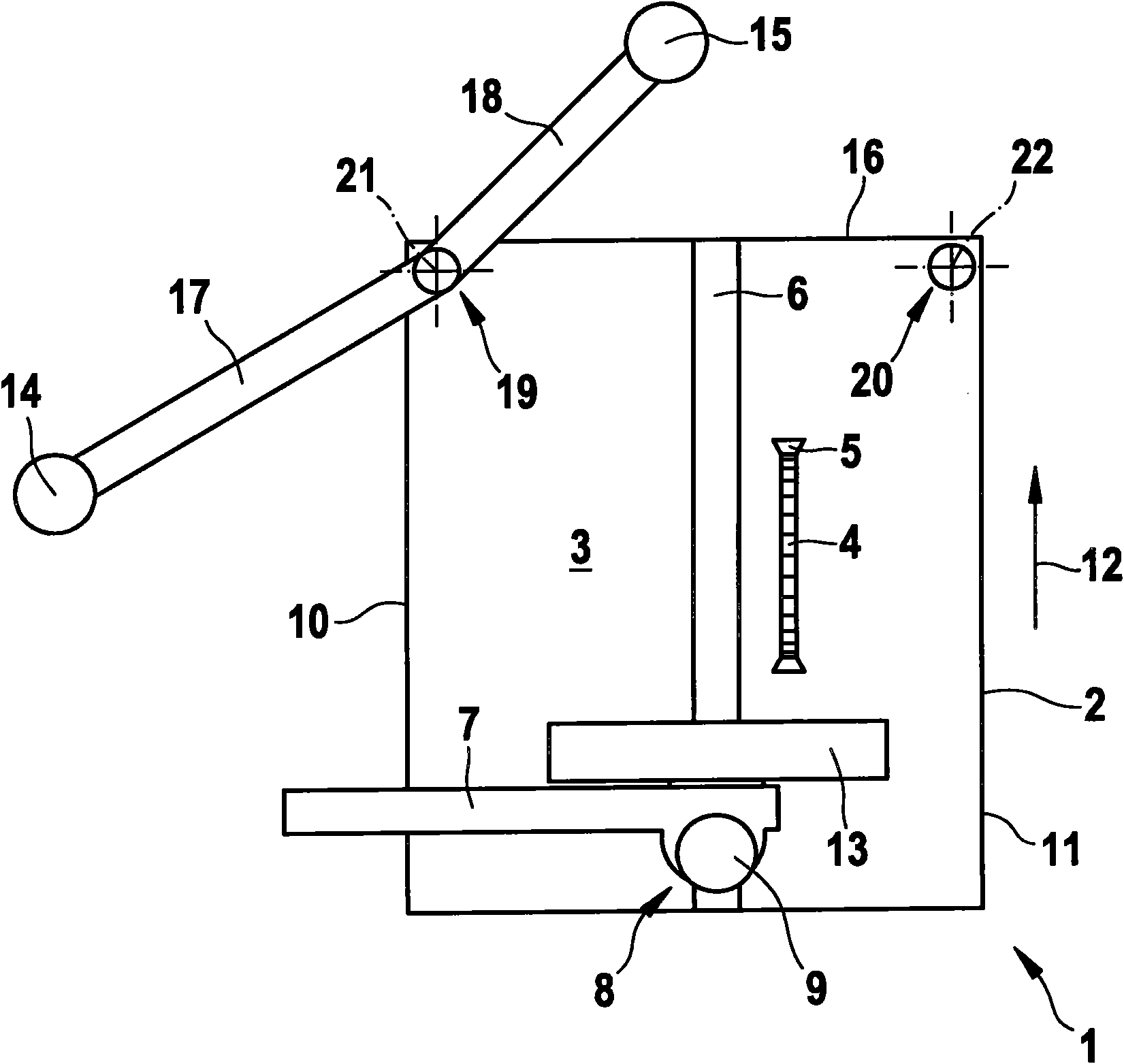
[0027] in figure 1 1 denotes the workbench of a machine tool configured as a circular saw. The single-piece or multi-piece structure of the table 2 has a table 3. The current working section of the saw blade 4 extends beyond the table top 3 at least during working operation, and the working section passes through the table top 2 in a longitudinally extending slot 5 of a corresponding size. The saw blade 4 is shown in its position perpendicular to the table top 3. In addition, in order to perform bevel cutting, the saw blade 4 can be deflected around a rotation axis extending parallel to the table surface 3 and can be adjusted to various angular positions relative to the table surface 3. The corresponding adjustment and support devices are the same as the lower structure of the workbench 1. figure 1 The view is covered by the platen 2 and is not shown.

[0028] The channel-like cut 6 extends parallel to the saw blade 4 or the slot 5 through which the saw blade passes. The cut ca...


PUM


Abstract

A workpiece support (14, 15) which is especially designed for work benches of machine tools forms a separate part of a workpiece support having a bench surface (3) and is supported so as to be pivotable in parallel to the bench surface (3), while projecting from the bench surface (3), via a pivoting arm (17, 18) which itself may form part of the workpiece support.

Description

Technical field [0001] The invention relates to a workbench for machine tools, in particular circular saws and / or swing saws, according to the preamble of claim 1 and a workpiece support device according to claim 13. Background technique [0002] The aforementioned types of workbenches are disclosed by practice. The table surface of these worktables that determines the plane of the table constitutes a support for the workpiece input to the saw. In order to ensure the necessary reliable and / or accurate operation of the workpiece for large workpieces that are often inconvenient to operate, a workpiece support of corresponding size is required. However, in practice, the size of the table top of the corresponding work table is not only limited by the following aspects: it is also necessary to operate smaller-sized workpieces and the tools located inside the table top must be located within the user’s access to the user who manipulates the workpiece. In the area. [0003] For portabl...

Claims


Application Information

Patent Timeline
IPC IPC(8): B23D47/02B27B5/16
CPCB23D47/025
Inventor R·富克斯
Owner ROBERT BOSCH GMBH
Why Eureka
Try Eureka