Illuminating apparatus

A light-emitting and light-guiding layer technology, applied in lighting devices, display devices, emergency protection devices, etc., can solve the problems of low chip utilization efficiency and large overall thickness of the lighting device, and achieve the effect of thin light utilization efficiency

Inactive Publication Date: 2010-01-13
ALPS ALPINE CO LTD
View PDF2 Cites 10 Cited by
  • Summary
  • Abstract
  • Description
  • Claims
  • Application Information

AI Technical Summary

Problems solved by technology

Therefore, the overall thickness dimension of the lighting device becomes larger
Moreover, because the light emitted by the light emitting device is incident on the plastic light guide member from the outside, the utilization efficiency of the light emitted by the chip in the light emitting device is very low.

Method used


Image

  • Illuminating apparatus
  • Illuminating apparatus
  • Illuminating apparatus

Examples


Embodiment Construction

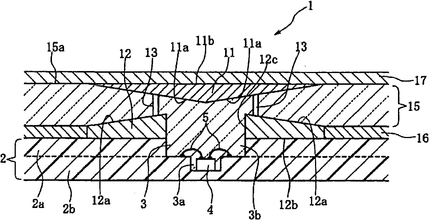
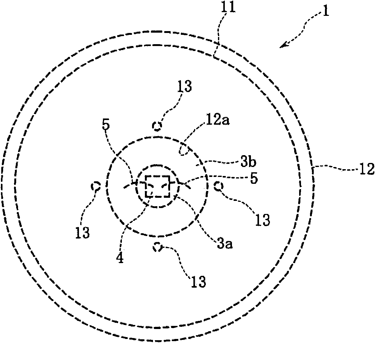
[0042] figure 1 It is a sectional view showing the lighting device 1 according to the first embodiment of the present invention, figure 2 It is a top view showing the above-mentioned lighting device 1 .

[0043] figure 1 and figure 2 The illustrated illuminating device 1 is arranged on the operating surface of a small electronic device such as a portable telephone, and is used for guiding the light emitted by the emitting element to the pressing operation part and illuminating the light that is arranged on the pressing operation part or on the operating surface thereof. surrounding lighting. Alternatively, it is used to guide light onto a partial lighting portion that displays characters, symbols, or numerals provided on the operation surface or the above-mentioned push operation portion. Alternatively, the lighting device 1 may be exposed on an operation surface of a small device or the like so as to be visible from the outside.

[0044] "Light guiding" described as "l...


PUM


Abstract

To provide an illuminating apparatus which is thinly configured and capable of efficiently guiding light emitted from a light emitting element to surrounding areas. ¢MEANS FOR SOLVING PROBLEMS! A recessed section (3) is formed on a substrate (2), a bare chip (4) of a light emitting diode is mounted in the recessed section (3); and the bare chip (4) and a conductive section on the substrate (2) are connected by conductive lines (5, 5). On the surface of the substrate (2), a second reflecting member (12), a supporting member (13), and a first reflecting member (11) are assembled, and a core layer (15) is formed by having a liquid synthetic resin flow and cure between the bare chip (4) and the first reflecting member (11). An interval between the bare chip (4) and the first reflecting member (11) is constantly kept fixed by the supporting member (13). Light emitted from the bare chip (4) enters a core layer (15), is reflected by reflecting surfaces (11a, 12a), and is guided to the surrounding areas.

Description

technical field [0001] The present invention relates to an illuminating device for illuminating operation parts of various electronic devices, and more particularly to an illuminating device capable of forming a thin structure and effectively transmitting light emitted by a light-emitting element. Background technique [0002] Various electronic devices such as audio equipment and portable electronic devices are equipped with light guide members that guide light emitted by light emitting devices such as LEDs to the operation surface. The light guided into the light guide member is used to illuminate the operation buttons provided on the operation surface and the display portion of fixed characters or numbers engraved on the operation surface. [0003] In the conventional lighting device disclosed in the following Patent Document 1, a light guide member formed of a resin plate such as an acrylic plate is mounted on the back side of the operation surface of an electronic devic...

Claims


Application Information

Patent Timeline
Patent Type & Authority Applications(China)
IPC IPC(8): F21V8/00F21S2/00G09F13/18H01H9/18F21Y101/02
CPCH01H2219/06H01L33/60H01H2219/062H01L33/483G02B6/0051H01H13/83G02B6/0053G09F13/18H01L2224/48091H01L2224/48227H01L2224/48464H01L2924/15153H01L2924/181H01L2924/00014H01L2924/00012
Inventor 冈本淳相原正巳伊藤直树伊势和贵
Owner ALPS ALPINE CO LTD
Why Eureka
Try Eureka