

Ring crush electrocardiogram chest lead connector
A technology of electrocardiogram and connectors, which is applied in the field of ring-pressure electrocardiogram chest lead connectors, can solve problems such as difficulty in achieving uniform smearing, and achieve the effect of uniform smearing
- Summary
- Abstract
- Description
- Claims
- Application Information
AI Technical Summary
Problems solved by technology
Method used
Image

Examples
Embodiment Construction
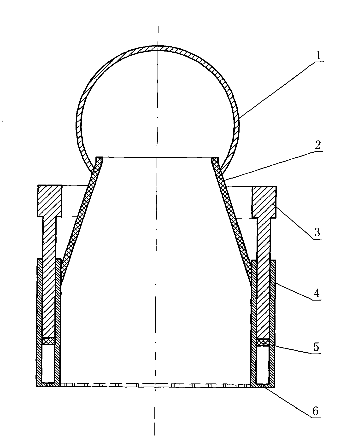
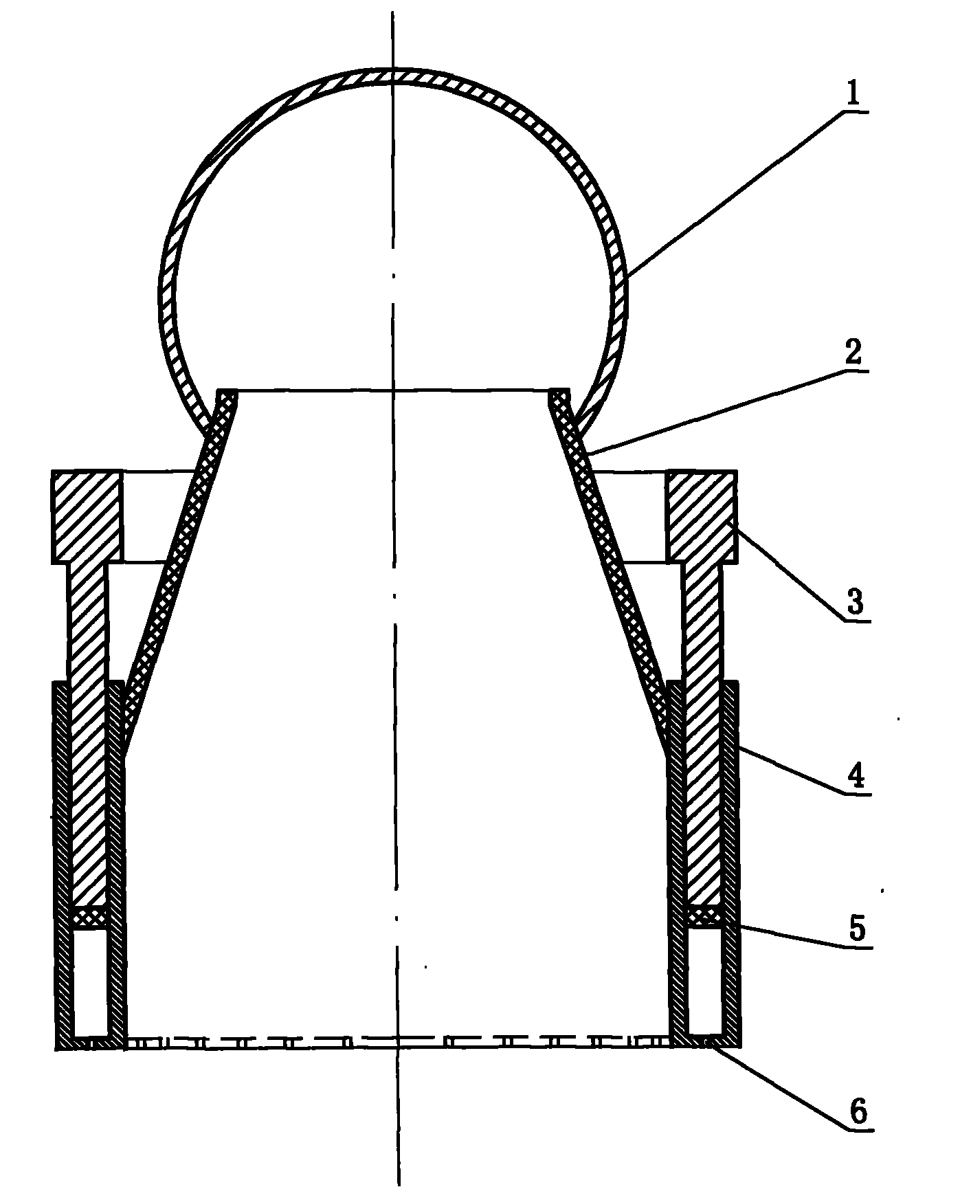
[0013] The present invention will be further described below in conjunction with the accompanying drawings and embodiments.
[0014] The ring pressure electrocardiogram chest guide connector is composed of a negative pressure bag 1, an electrode cup 2, a hand pressure cylinder 3, a ring groove cylinder 4, a rubber ring 5 and a liquid outlet 6. The ring groove cylinder 4 is a cylindrical body with an annular groove opening upward, and the bottom of the ring groove cylinder 4 has liquid outlet holes 6 evenly distributed along the circumference. The diameter of the outlet hole 6 is between 0.3mm-0.8mm. The hand press cylinder 3 is a cylindrical body with a T-shaped longitudinal section, and the lower end of the hand press cylinder 3 is in the annular groove of the ring groove cylinder 4 and has a dynamic cooperation relationship with the ring groove cylinder 4 . A circle of rubber rings 5 is bonded to the bottom of the hand press cylinder 3 . The electrode cup 2 is in the sha...
PUM
 Abstract
Description
Claims
Application Information