Metal tool box structure and forming method thereof
A technology of metal tools and forming methods, which is applied in the field of tool boxes, can solve problems such as loose lids, poor appearance aesthetics, and uneven lids, and achieve the effects of increasing strength and durability, improving service life, and improving appearance aesthetics
- Summary
- Abstract
- Description
- Claims
- Application Information
AI Technical Summary
Problems solved by technology
Method used
Image

Examples
Embodiment Construction
[0041] The above and other features and advantages of the present invention will be described in detail below with reference to the accompanying drawings.
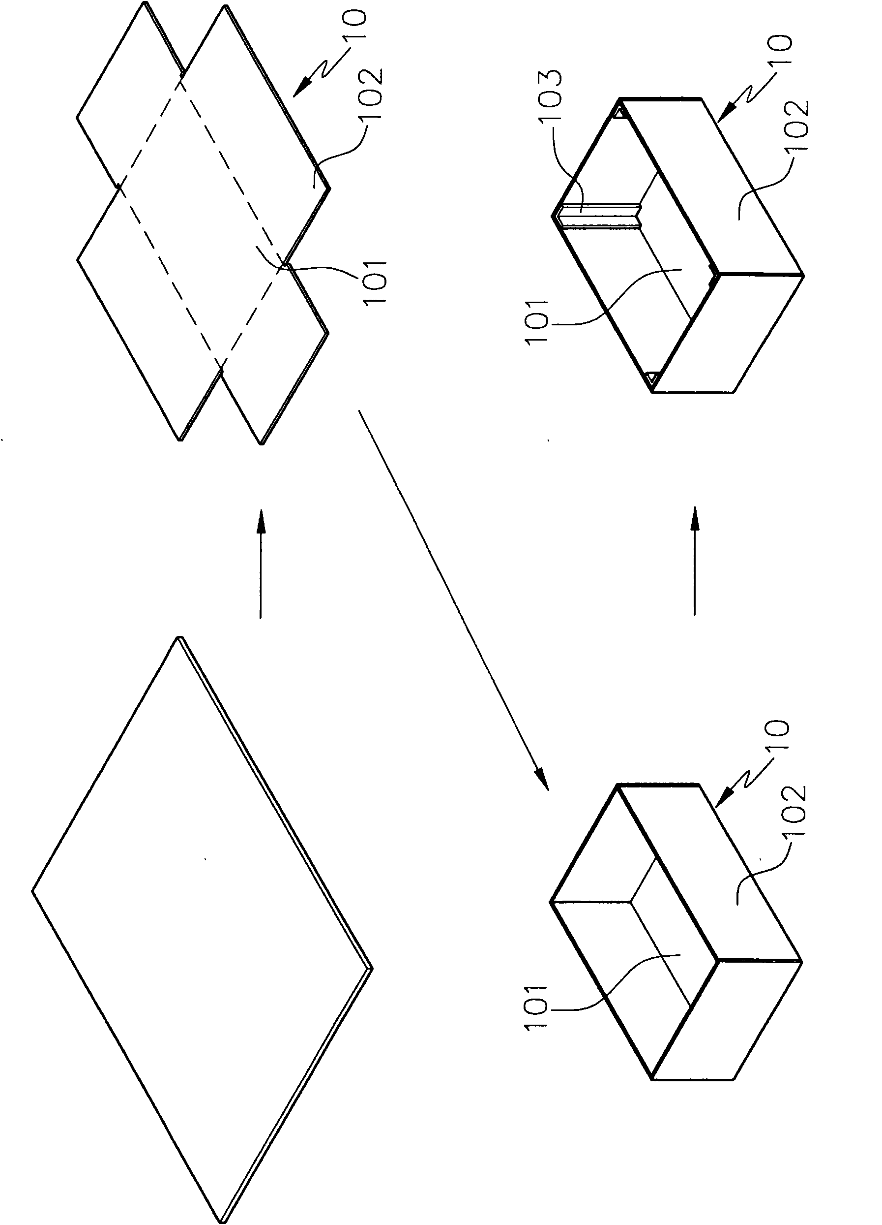
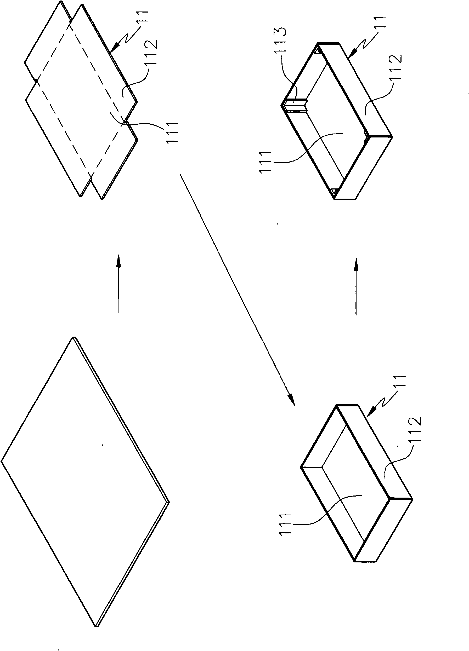
[0042] Such as Figure 9 , Figure 10 As shown, when the present invention is making the seat body 30 of the metal tool box, it first takes an appropriate metal plate for extraction processing, and uses a mold to integrally stretch and form the base body 30 at the center of the metal tool box. , the base 30 is formed with a bottom plate 301 and a side plate 302 with arc angles, and at the same time, several grooves 303 are formed outside the bottom plate 301; please refer to Figure 9 , 11 As shown, the base body 30 rough blank is then punched to form several perforations 304 on the groove 303 of the base body 30 rough blank. refer to Figure 9 , 12 As shown, the edge removal process is carried out, which is to remove the remaining material around the rough base of the seat body 30 by punching and shearing; refer to ...
PUM
 Abstract
Description
Claims
Application Information
 - Generate Ideas
- Intellectual Property
- Life Sciences
- Materials
- Tech Scout
- Unparalleled Data Quality
- Higher Quality Content
- 60% Fewer Hallucinations
Browse by: Latest US Patents, China's latest patents, Technical Efficacy Thesaurus, Application Domain, Technology Topic, Popular Technical Reports.
© 2025 PatSnap. All rights reserved.Legal|Privacy policy|Modern Slavery Act Transparency Statement|Sitemap|About US| Contact US: help@patsnap.com