Actuation balance-free type single-reducing coupling

A coupling and balanced technology, which is applied in the field of single variable diameter couplings that are not used as dynamic balance, can solve the problems of unsightly appearance, complex coupling structure, cumbersome operation procedures, etc., and achieve saving raw materials and joint clearance Small, reduce the effect of starting current power

Inactive Publication Date: 2010-01-20
李文聪
View PDF0 Cites 7 Cited by
  • Summary
  • Abstract
  • Description
  • Claims
  • Application Information

AI Technical Summary

Problems solved by technology

When the motor is started frequently, the two ends of the coupling will inevitably vibrate or even deform, which will affect the axial, radial and angular offset caused by the misalignment of the two shafts. Therefore, the existing coupling All shaft couplings need to be dynamically balanced to balance the mass imbalance caused by the center to overcome the above-mentioned possible situations, but the structure of this coupling is complicated and the operation process is cumbersome; at the same time, in order to increase the weight of the shaft coupling Smooth, unavoidable defects in its appearance caused by drilling holes in its body

Method used


Image

  • Actuation balance-free type single-reducing coupling
  • Actuation balance-free type single-reducing coupling
  • Actuation balance-free type single-reducing coupling

Examples


Embodiment 1

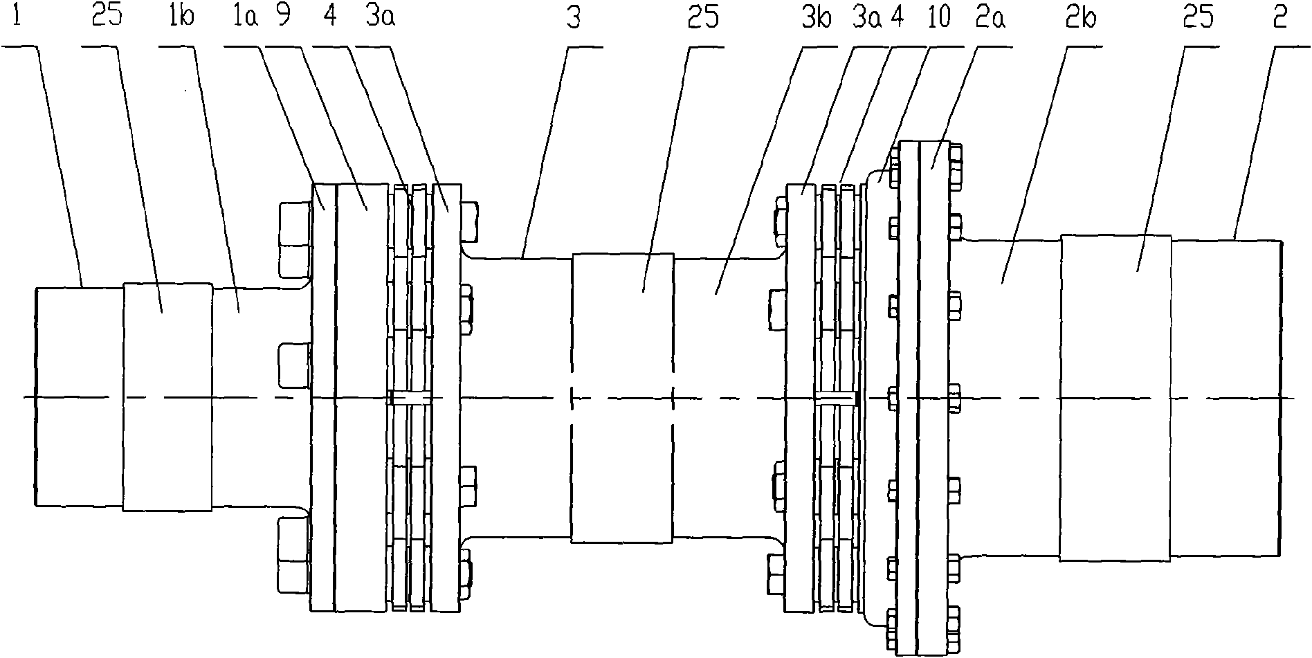
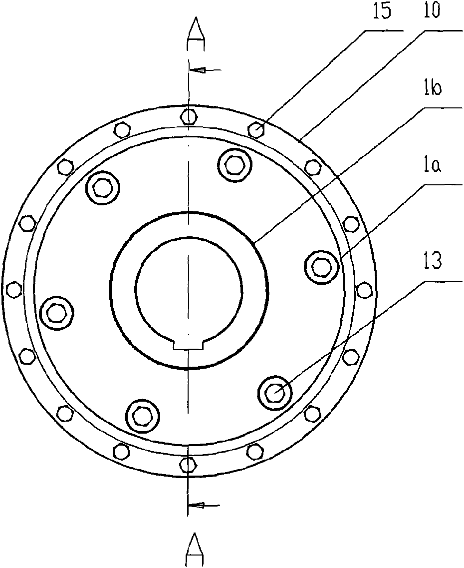
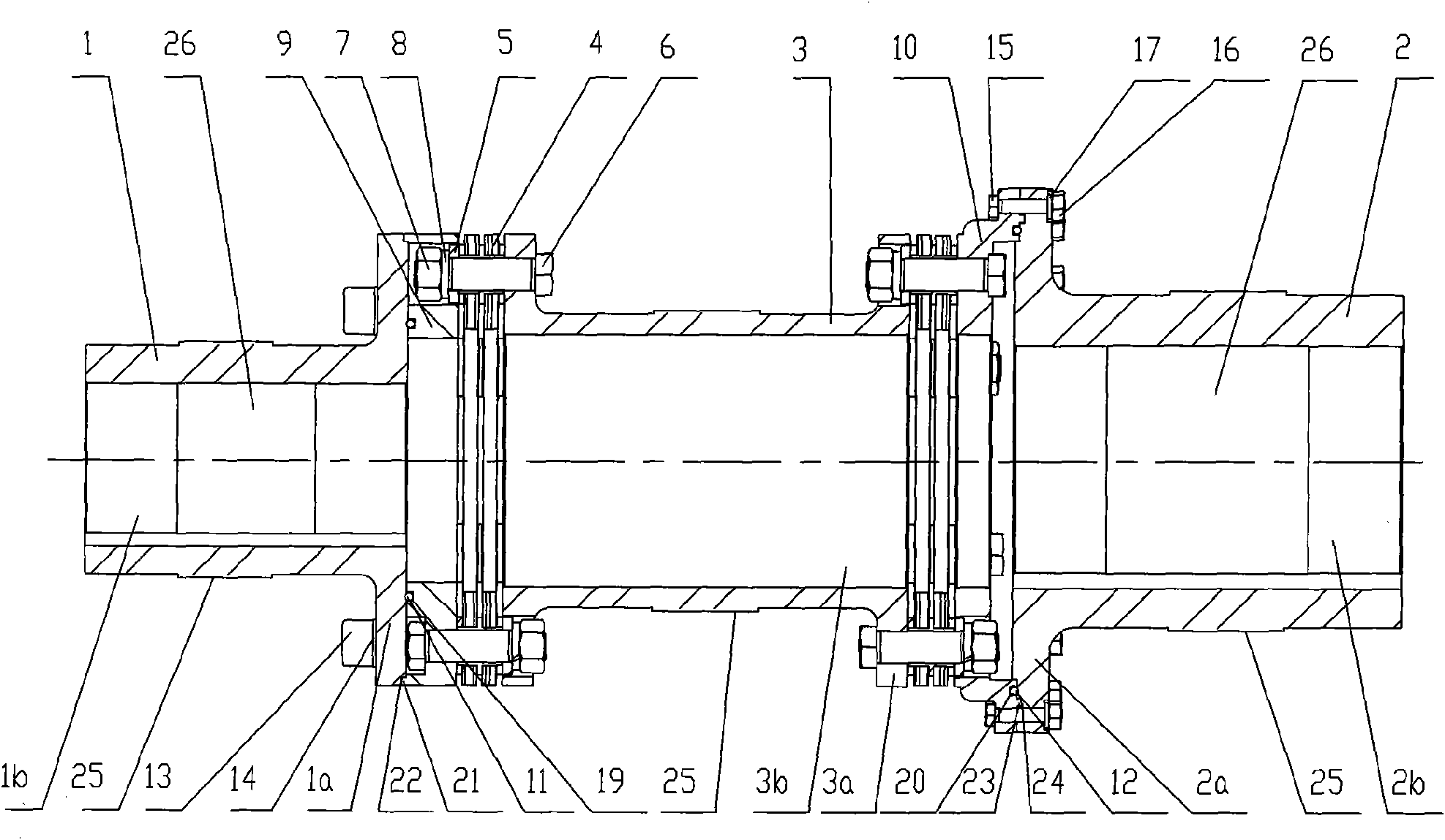
[0027] Such as Figure 1-4 As shown, the coupling of the present invention includes two half-couplings 1, 2, an intermediate section 3, two laminated diaphragm sets 4, a butt joint disc 9, a reducing disc 10 and two elastic rings 11, 12. The elastic rings are preferably high-strength elastic rings 11 and 12 made of polyurethane and high-strength rubber. The outer diameter of the docking disc is equal to the outer diameter of the flange of the half-coupling connected to it , the diameter reducing disc 10 is a flange whose diameter gradually increases from the inside to the outside, and a disc edge with the same diameter as the flange of the half-coupling is provided on the outer disc surface, and the laminated diaphragm group 4 Use double-sided rivets to penetrate dozens of elastic sheets at both ends, and then install two rivet caps, which are stamped twice by hydraulic force. The shafts of the two half-couplings 1, 2 and the middle section 3 are A ring of outer bosses 25 are...

Embodiment 2

[0031] The structure and connection relationship of the shaft coupling described in this example are the same as those in Example 1, except that:

[0032] In use, in order to better realize the assembly of the middle section, three elastic devices 18 for adjusting the distance between the docking disc and the reducing disc 10 are installed between the docking disc 9 and the reducing disc 10 of the coupling described in this example ,Such as Figure 5As shown, the elastic device 18 includes two bolts 18a, 18b and a long nut 18c. The long nut in this example adopts a turnbuckle nut with positive and negative threaded holes at both ends, and the two bolts have positive and negative threads at both ends. Straight bolts, one end of the bolt 18a passes through the flange plate 3a of the middle section and the laminated diaphragm group 4 in sequence, and is screwed with the screw hole on the docking plate 9, and the other end of the bolt 18a is screwed with the threaded hole of the l...


PUM


Abstract

The invention relates to an actuation balance-free type single-reducing coupling which comprises two half-couplings, an intermediate section and a diaphragm group, wherein each of the two half-couplings is an axis connecting sleeve provided with a flange at one end; the intermediate section is an axis connecting sleeve provided with flanges at both ends; the external side of the flange at one end of the intermediate section is sequentially connected with the diaphragm group and a butting disc; the external side of the flange at the other end of the intermediate section is sequentially connected with the diaphragm group and a reducing disc; the two half-couplings are respectively connected with the butting disc and the reducing disc in a bayonet positioning mode; the axis connecting sleeves of the two half-couplings and the intermediate section are respectively provided with an outer lug boss; and the diaphragm group is laminated and produced in such a way that all elastic flakes are threaded and connected by double-faced rivets and hydraulically punched. The actuation balance-free type single-reducing coupling can meet precision requirements of 2.5 level dynamic balance without actuation balance at the rotating speed of 10000r/min or below, thereby omitting the working procedure of actuation balance and overcoming the defect of unprepossessing appearance caused by the drilling of the coupling.

Description

technical field [0001] The invention belongs to a transmission device, in particular to an unused dynamic balance type single variable diameter coupling. Background technique [0002] The coupling is used to transmit power and is used to connect the two shafts of the main machine and the working machine. The two shafts cannot be separated when the machine is running. Only after the machine stops and the connection is disassembled can the two shafts be separated. When the motor is started frequently, the two ends of the coupling will inevitably vibrate or even deform, which will affect the axial, radial and angular offset caused by the misalignment of the two shafts. Therefore, the existing coupling All shaft couplings need to be dynamically balanced to balance the mass imbalance caused by the center to overcome the above-mentioned possible situations, but the structure of this type of coupling is complex and the operation process is cumbersome; at the same time, in order to ...

Claims


Application Information

Patent Timeline
Patent Type & Authority Applications(China)
IPC IPC(8): F16D3/56
Inventor 李文聪
Owner 李文聪
Why Eureka
Try Eureka