Piston and method of manufacture

A technology of piston and piston skirt, applied in the field of piston and manufacturing, can solve the problems of unknown, impossible induction coil, unknown use, etc., and achieve the effect of precise heating

Inactive Publication Date: 2010-01-20
FEDERAL MOGUL CORP
View PDF3 Cites 0 Cited by
  • Summary
  • Abstract
  • Description
  • Claims
  • Application Information

AI Technical Summary

Problems solved by technology

As can be seen, this structure presents challenges for joining the two parts by means of induction heating welding due to the limited access to the area where the joining surfaces are located and in the case of internal cooling channels it is not possible to access adjacent to the mating The location of any induction coils on the engagement surface
On the basis of the known prior art in the piston art, it is not known that there is a suitable technique for induction heating welding of complex piston structures such as that shown in the above-mentioned '642 patent, and since such induction heating Practical difficulties of applying the technique to complex piston structures with multiple radially spaced engagement surfaces, no such appropriate technique is known to have been used

Method used


Image

  • Piston and method of manufacture
  • Piston and method of manufacture
  • Piston and method of manufacture

Examples


Embodiment Construction

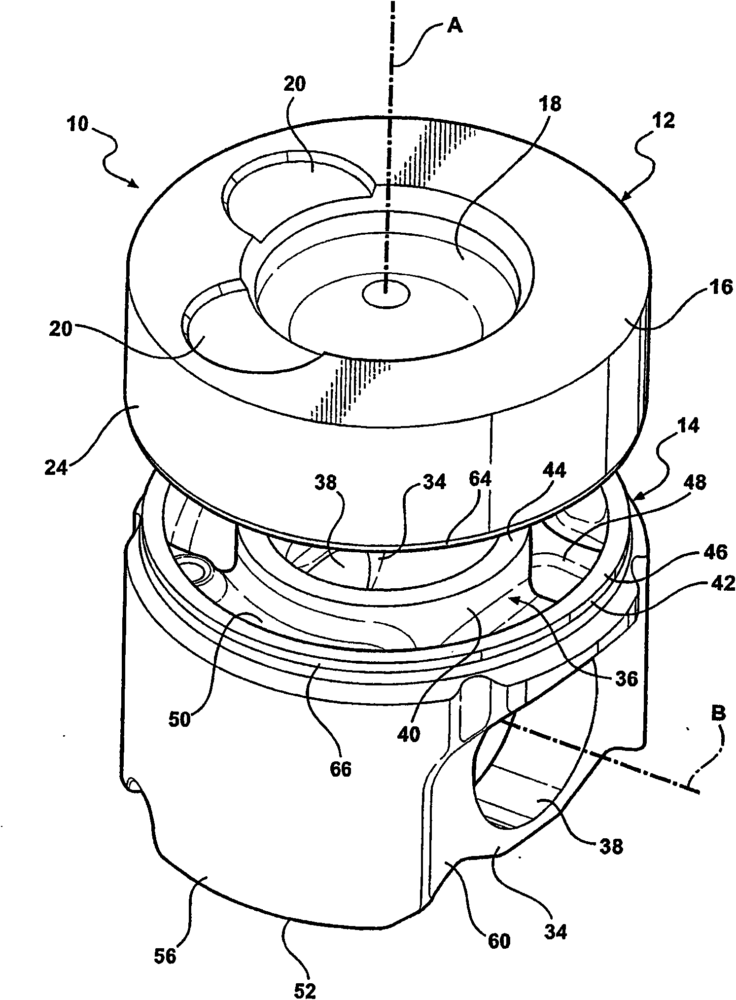
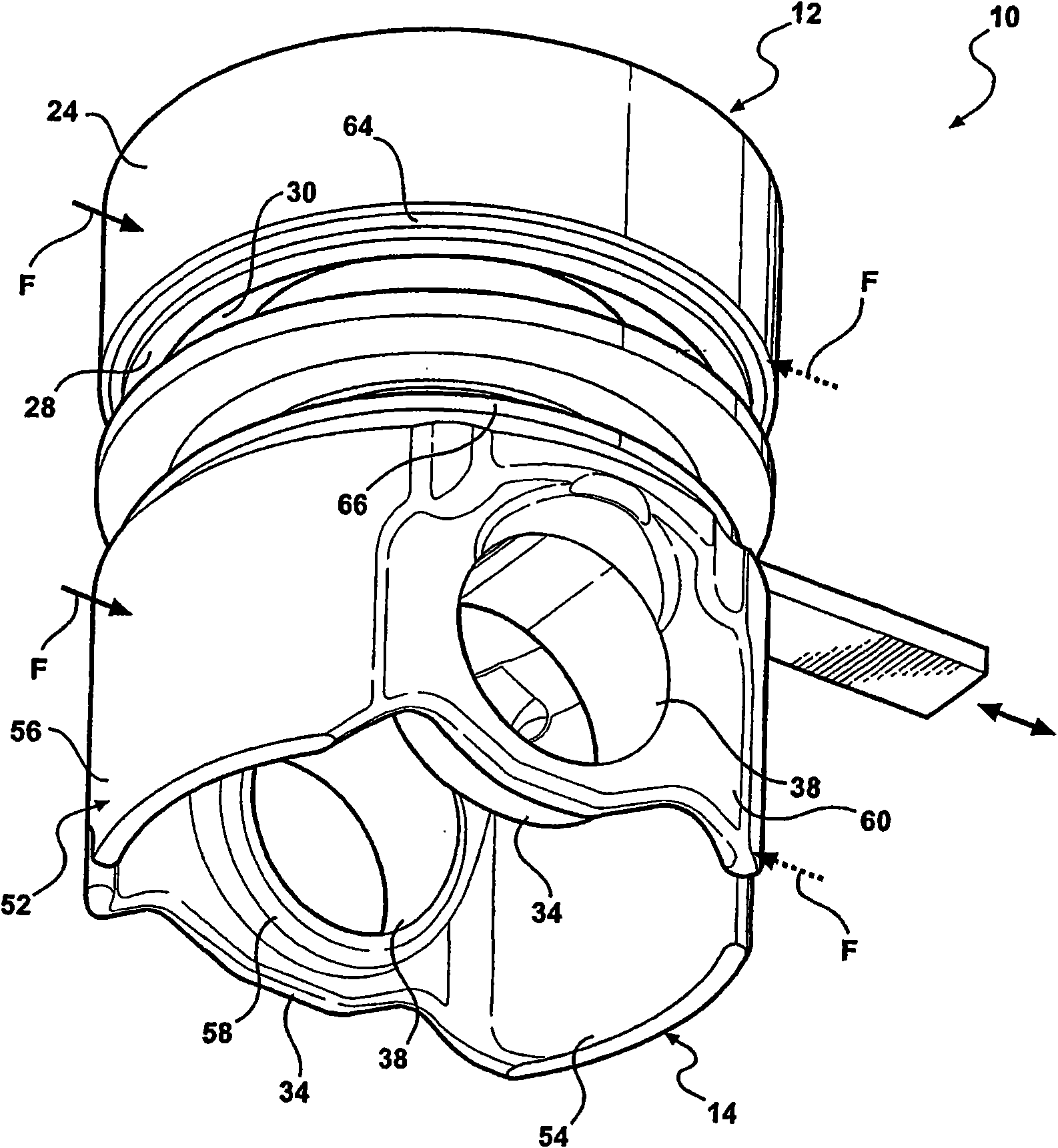
[0024] A piston constructed in accordance with a preferred embodiment of the present invention, indicated in the drawings with the reference numeral 10, is made of at least two parts, which are formed separately from each other, providing at least one set, preferably at least two sets, of circumferentially extending The mating joining surfaces are initially spaced apart from each other and heated to a temperature sufficient to weld the parts, after which heating of the surfaces is terminated to join the surfaces to each other to achieve a permanent weld between the parts.

[0025] In the illustrated embodiment, the piston 10 includes a first component 12 and a second component 14 . The two parts 12, 14 are made of metal, preferably alloy steel, however, the invention is not limited to these materials. The first and second parts may be cast, forged, made from powdered metal or made from any other method used to make metal parts. The alloys used for the first and second parts 1...


PUM


Abstract

A piston particularly adapted for heavy-duty diesel engine applications is fabricated from separate parts having circumferentially extending joining surfaces that are heated prior to bonding to an elevated temperature sufficient to enable bonding of the joining surfaces, and thereafter the joining surfaces brought into contact with one another and twisted to attain a permanent metallurgical weld at the interface of the joining surfaces.

Description

[0001] This application is a divisional application of the patent application with the application number "200380107217.2", the filing date being November 5, 2003, and the invention title being "piston and manufacturing method". Background of the invention [0002] Various methods are known for joining separately formed parts of the piston to create the piston structure. One such method is friction welding, in which one part of the piston is rotated at high speed while pressing against the other part, and the resulting frictional energy generates enough heat to bond the two parts together. Other techniques include resistance welding, induction heating welding, etc., wherein after the two parts are brought into contact with each other, a flux is passed through the joining surfaces, which heats them sufficiently to join the two surfaces to each other. [0003] U.S. Patent No. 5,150,517 is an example of a friction welding method, and U.S. Patent No. 6,291,806 is another example o...

Claims


Application Information

Patent Timeline
IPC IPC(8): F16J1/00F02F3/20
Inventor C·里贝罗T·埃格雷尔R·盖泽
Owner FEDERAL MOGUL CORP
Why Eureka
Try Eureka