

Body insulation structure of dry-type transformer with three-dimensional rolled iron core and manufacturing process thereof
A dry-type transformer, three-dimensional technology, applied in the direction of transformer/inductor coil/winding/connection, coil manufacturing, etc., can solve the problem of uneven force on the insulation coil of the body, improve stability and resist sudden short circuit Ability, uniform force, the effect of reducing manufacturing cost
- Summary
- Abstract
- Description
- Claims
- Application Information
AI Technical Summary
Problems solved by technology
Method used
Image

Examples
Embodiment 1
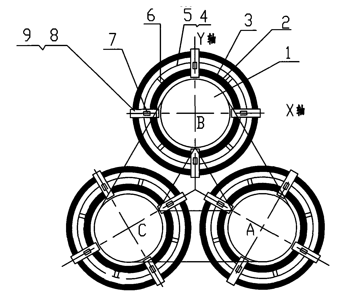
[0015] Example 1: Three-dimensional three-dimensional wound dry-type core transformer, the stays are fixed on the low-voltage coil
[0016] see figure 1 The structure of the insulator body in this embodiment consists of a three-dimensional wound core 1, a high-voltage coil 2, a low-voltage coil 3, an insulating sheet 4, a pre-impregnated insulating material 5, a stay 6, a cushion block 7 for supporting and compressing the coil, a hard Pad block 8, pressure screw 9 constitute. After the transformer core is completed, use special winding equipment to wind the low-voltage coil, and then support and fix the insulating sheet 4 and pre-impregnated insulating material 5 on the low-voltage coil through the stay 6 to form an insulating tube or insulating sheet 4 and pre-impregnated insulating material 5. The stays are fixed on the high-voltage coil to form an insulating cylinder. The former is to directly support the low-voltage coil by the stay 6 after the low-voltage coil is wound ...
Embodiment 2
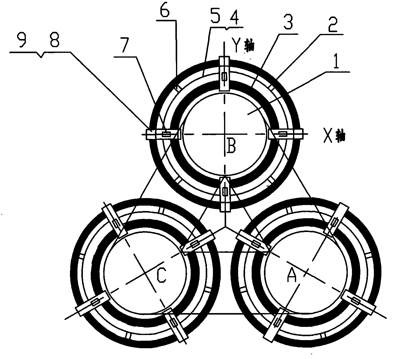
[0018] Embodiment 2: Dry-type transformer with non-encapsulated (cake-type) coil
[0019] see figure 2 In this embodiment, before the high-voltage coil is wound, the insulating sheet 4 and the pre-impregnated insulating material 5 are wrapped on the winding mold to form an insulating cylinder, and then the high-voltage coil is wound by a stay, which is generally used for non-encapsulated (cake-type) coils on the dry-type transformer. The prepreg material 5 can be a semi-cured resin-impregnated insulating paper or cloth with a width such as an insulating cylinder, or a semi-cured resin-impregnated insulating tape with a certain width. Other structures are the same as in Embodiment 1.
[0020] The present invention is also suitable for other types of oil-immersed transformers. The structure of the insulating cylinder is also suitable for planar wound core transformers.
PUM
 Abstract
Description
Claims
Application Information