Circuit for regulating and controlling output power of power supply

A technology of power regulation and power output, which is applied in the direction of output power conversion device, conversion of DC power input to DC power output, conversion of AC power input to AC power output, etc. Work performance is affected by environmental changes, control signal stability is not high, etc., to achieve the effect of suppressing common mode interference

Inactive Publication Date: 2010-01-20
HONG FU JIN PRECISION IND (SHENZHEN) CO LTD +1
View PDF0 Cites 3 Cited by
  • Summary
  • Abstract
  • Description
  • Claims
  • Application Information

AI Technical Summary

Problems solved by technology

However, the working performance of the self-excited circuit is greatly affected by environmental changes, especially its poor anti-common-mode interference ability, which makes the stability of the control signal for regulating the output power of the power supply not high

Method used


Image

  • Circuit for regulating and controlling output power of power supply

Examples


Embodiment Construction

[0007] The present invention will be described in further detail below in conjunction with specific embodiment with reference to accompanying drawing:

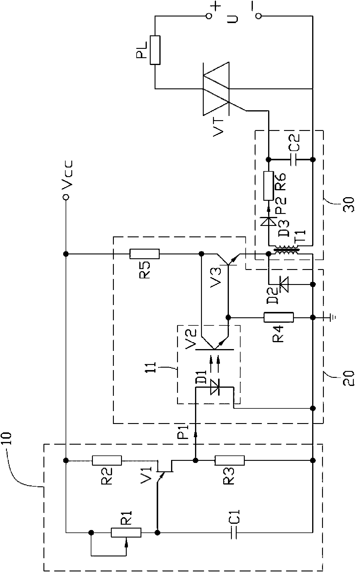
[0008] Please refer to figure 1 The power supply output power control circuit of the present invention is used to control the output power of a power supply U to a load PL, and its preferred embodiment includes a signal generation circuit 10, a photoelectric coupling circuit 20, a voltage transformation conversion circuit 30 and a thyristor VT. The power supply U can be a DC power supply or an AC power supply.

[0009] The signal generating circuit 10 includes three resistors R1, R2, R3, a capacitor C1 and a unijunction transistor V1, the resistor R1 is a variable resistor, and the emitter of the unijunction transistor V1 passes through the resistor R1 is connected to a DC power supply Vcc and grounded through the capacitor C1, the first base of the unijunction transistor V1 is grounded through the resistor R3, and the second...


PUM


Abstract

The invention provides a circuit for regulating and controlling an output power of a power supply, which comprises signal generating circuit, a photoelectric coupling circuit, a transformation switching circuit and a thyristor. The thyristor is connected between the power supply and a load. The signal generating circuit generates a first pulse signal having an adjustable duty ratio and provides the first pulse signal to the photoelectric coupling circuit. When the first pulse signal has a high electric level, the photoelectric coupling circuit is closed and the photoelectric coupling circuit outputs a sinusoidal signal. The sinusoidal signal is converted into a second pulse signal through the transformation switching circuit so as to control the on and off of the thyristor. When the second pulse signal has a high electric level, the thyristor is turned on and the power supply supplies a power to the load; and when second pulse signal has a low electric level, the thyristor is turned off and the power supply does not supply the power to the load. The circuit for regulating and controlling the output power of the power supply uses the photoelectric coupling circuit to isolate the signal generating circuit and the transformation switching circuit. The photoelectric coupling circuit can effectively inhibit common code interference, and the signal generating circuit regulates and controls the output power of the power supply in unit time by regulating the duty ratio of the first pulse signal.

Description

technical field [0001] The invention relates to a power supply output power regulating circuit. Background technique [0002] Power supply is a widely used power supply device, and its output power control technology is very important for the stability of electronic equipment in various environments. Generally speaking, the driving stage of the power output power regulating circuit uses a self-excited circuit to generate a control signal, and then regulates the output power of the power supply. However, the working performance of the self-excited circuit is greatly affected by environmental changes, especially its ability to resist common-mode interference is poor, which makes the stability of the control signal for regulating the output power of the power supply not high. How to provide a circuit capable of stably regulating the output power of the power supply has become an urgent problem to be solved. Contents of the invention [0003] In view of the above, it is nece...

Claims


Application Information

Patent Timeline
Patent Type & Authority Applications(China)
IPC IPC(8): H02M1/06H02M3/135H02M5/257
Inventor 赵泉亮龙俊成
Owner HONG FU JIN PRECISION IND (SHENZHEN) CO LTD
Why Eureka
Try Eureka