Aerial coolant cold source system

A coolant and cold source technology, which is applied in the field of aviation coolant cold source system, can solve the problem that the output power of the pump body cannot be adjusted in time, and achieve the effects of reducing emissions, saving costs, and reducing waste

Pending Publication Date: 2018-06-12
成都弗格森液压机电有限公司
View PDF5 Cites 0 Cited by
  • Summary
  • Abstract
  • Description
  • Claims
  • Application Information

AI Technical Summary

Problems solved by technology

[0003] The purpose of the present invention is to solve the problem that the output power of the pump body in the above-mentioned aviation coolant cold source system cannot be adjusted in time, which causes the pressure of the output liquid of the pump to exceed the pressure of the parts that need to be cooled. The present invention provides an aviation cooling system. Liquid Cooling System

Method used


Image

  • Aerial coolant cold source system
  • Aerial coolant cold source system
  • Aerial coolant cold source system

Examples


Embodiment 1

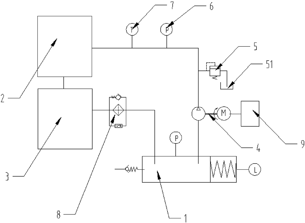
[0045] The technical solution of this embodiment is: an aviation coolant cold source system, including a pressurized liquid storage assembly 1, a pump set 4, a heat load 2, a heat sink 3, and a filter assembly 8 connected end to end in sequence; Component 1, pump set 4, heat load 2, cooling device 3 and filter component 8 are connected in sequence through pipelines and form a circulation system;

[0046] A safety valve 5, a second pressure sensor 6 and a temperature sensor 7 are sequentially arranged on the pipeline between the pump group 4 and the heat load 2 from the pump group 4 along the direction of the heat load 2;

[0047] A liquid outlet pipe is connected to the liquid outlet of the safety valve 5, and a liquid storage tank 51 is arranged below the outlet of the liquid outlet pipe.

[0048] Such asfigure 1 As shown, the coolant stored in the pressurized liquid storage assembly 1 is pumped out by the pump group 4 into the pipeline for circulation. When the pressure at t...

Embodiment 2

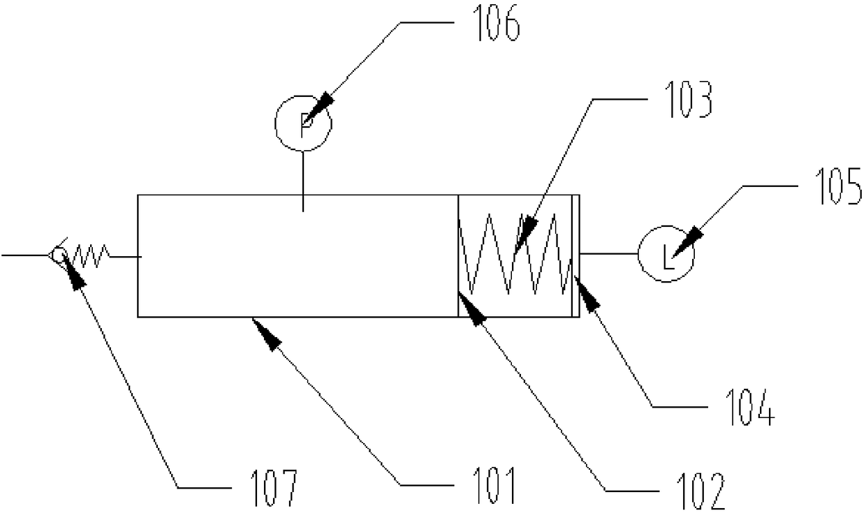
[0050] On the basis of Embodiment 1, the technical solution of this embodiment is: the pressurized liquid storage assembly 1 includes a liquid storage tank 101, and a displacement sensor 104 and a booster spring are sequentially arranged in the liquid storage tank 101 from one end to the other end 103 and the piston assembly 102.

[0051] Such as figure 2 As shown, the displacement sensor 104 measures the moving distance of the booster spring 103, thereby reflecting the increased pressure of the coolant in the liquid storage tank 101, which is used to increase the pressure of the coolant entering the pump set 4, so that the pressure of the pump set 4 outlet The pressure of the coolant is not too low.

Embodiment 3

[0053] Based on the first embodiment, the technical solution of this embodiment is that the liquid storage tank 101 is provided with a liquid injection valve 107 , a first pressure sensor 106 and a liquid level sensor 105 .

[0054] Such as figure 2 As shown, the first pressure sensor 106 is used to measure the pressure of the cooling liquid in the liquid storage tank 101, and the liquid injection valve 107 is used to supplement the amount of cooling liquid in the liquid storage tank 101, so as to avoid the change of the cooling liquid volume caused by the temperature change , the liquid level sensor 105 responds to the change in the volume of the cooling liquid in the liquid storage tank 101 .


PUM


Abstract

The invention discloses an aerial coolant cold source system. The aerial coolant cold source system comprises a pressurizing liquid storage component, a pump unit, a thermal load part, a heat radiating device and a filter component which are sequentially connected end to end; the pressurizing liquid storage component, the pump unit, the thermal load part, the heat radiating device and the filter component sequentially communicate with one another through pipelines to form a circulation system; the pipeline between the pump unit and the thermal load part is sequentially provided with a safety valve, a second pressure sensor and a temperature sensor in a direction from the pump unit to the thermal load part; a liquid outlet of the safety valve is connected with a liquid discharging pipeline;and a liquid storage tank is arranged below the outlet of the liquid discharging pipeline. According to the aerial coolant cold source system disclosed by the invention, the temperature and the pressure of a coolant which enters the thermal load part are guaranteed to be within an allowable range so as to guarantee smooth running of a liquid cooling system, and the service lives of to-be-cooled components and parts are prolonged.

Description

technical field [0001] The invention belongs to the technical field of aviation cooling, and in particular relates to an aviation cooling liquid cold source system. Background technique [0002] Since the coolant in the aviation coolant cold source system is mostly corrosive (such as 65# coolant), and the medium has no lubricating properties, when the coolant is pressurized by the pressurized liquid storage component, it is pumped out by the pump body. The output power of the pump cannot be adjusted in time, so the pressure of the coolant flowing out of the outlet of the pump body is often greater than the pressure of the parts that need to be cooled, which will cause the deformation of the parts and affect the normal use of the parts. Contents of the invention [0003] The purpose of the present invention is to solve the problem that the output power of the pump body in the above-mentioned aviation coolant cold source system cannot be adjusted in time, which causes the pr...

Claims


Application Information

Patent Timeline
Patent Type & Authority Applications(China)
IPC IPC(8): F25D17/02
CPCF25D17/02
Inventor 罗超黄泰波唐德刚罗珊林权谢随江贺睿
Owner 成都弗格森液压机电有限公司
Why Eureka
Try Eureka