Drive device for the spindles of a ring spinning machine

A technology of ring spinning machine and driving device, applied in spinning machine, continuous winding spinning machine, textile and papermaking, etc., can solve the problem of synchronous operation of tangential transmission belt without mentioning

Inactive Publication Date: 2010-01-20
OERLIKON TEXTILE GMBH & CO KG
View PDF3 Cites 8 Cited by
  • Summary
  • Abstract
  • Description
  • Claims
  • Application Information

AI Technical Summary

Problems solved by technology

The problem of synchronous operation of tangential belts is not mentioned here

Method used


Image

  • Drive device for the spindles of a ring spinning machine
  • Drive device for the spindles of a ring spinning machine
  • Drive device for the spindles of a ring spinning machine

Examples


Embodiment Construction

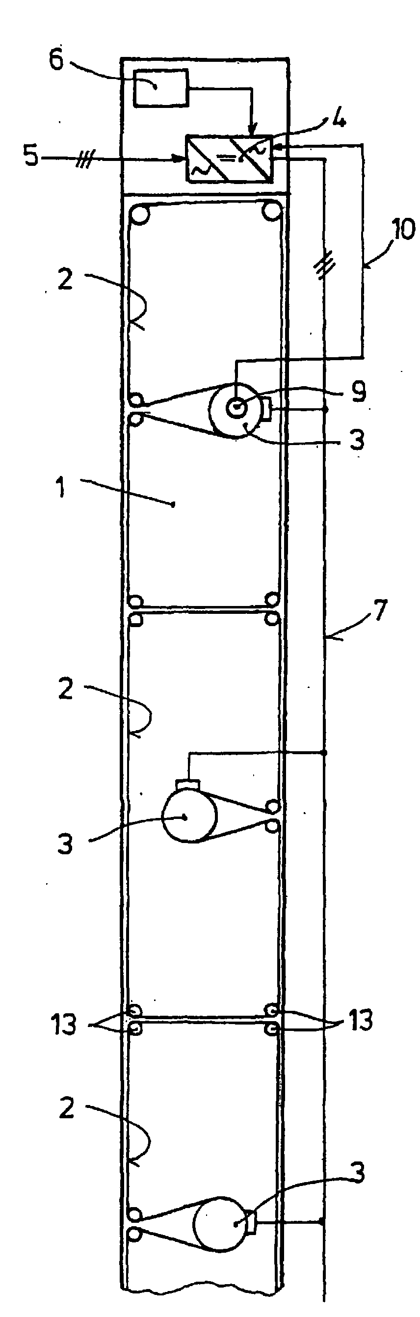
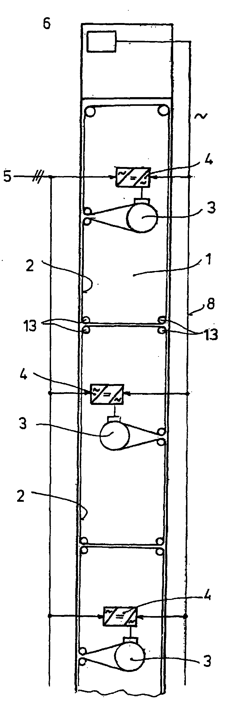
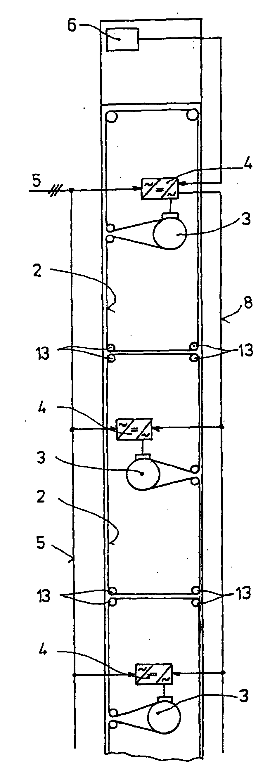
[0029] figure 1 A plan view of a ring spinning machine 1 is shown, which has a plurality of spindles (not shown here) on both longitudinal sides, which are driven in sections by means of tangential drive belts 2 . Each tangential belt drives a plurality of spindles on both sides of the machine, while each tangential belt itself is driven by means of an electric motor 3 . These electric motors are designed as synchronous motors. The feed current for these electric motors is generated by a frequency converter 4 which, via an intermediate DC circuit, generates alternating (polyphase) electricity of a certain frequency (the frequency of which is preferably variable) from the frequency of the grid 5 . The control of this feed frequency takes place in the form of the spindle speed which is predetermined by the machine controller 6 via an interface for the frequency converter 4 . Specifically, the acceleration of the spindle when it is started and the reduction of the rotational sp...


PUM


Abstract

In order to ensure the synchronous operation of the tangential belt driving the spindles of a ring spinning machine in sections, the electric drive motors (3) of the tangential belts (2) are configured as synchronous motors. They are supplied via a common frequency converter or individual frequency converters (4). The supply frequency is transmitted to the individual frequency converters by means of the machine controller (6) in the form of the desired spindle rotational speed.

Description

technical field [0001] The invention relates to a drive for a plurality of spindles of a ring spinning machine, which has a plurality of tangential belts which drive the spindles in sections and which can each be driven by an electric motor. Background technique [0002] DD 287 961 A5 and DD 287 962 A5 disclose drives for working units of spinning or twisting machines, which are driven in sections via a plurality of tangential drive belts. The type of these drive motors is not described. The problem of synchronous operation of tangential drive belts is not mentioned. [0003] DE 34 41 230 discloses such a drive in which a section tangential belt is driven by an asynchronous motor. Asynchronous motors do not run synchronously, especially if the asynchronous motors are not loaded with the same load. Therefore, in order to obtain the same yarn quality on all spindles of the ring spinning machine, it must be ensured that the tangential belts run synchronously in all sections....

Claims


Application Information

Patent Timeline
Patent Type & Authority Applications(China)
IPC IPC(8): D01H1/24D01H1/241
CPCD01H1/24D01H1/241
Inventor 彼得·曼恩京特·诺伊布格
Owner OERLIKON TEXTILE GMBH & CO KG
Why Eureka
Try Eureka