Apparatus and method comprising deformable lens element

A technology of anamorphic lenses and components, applied in the direction of lenses, optical components, electrical components, etc., can solve the problems of minimization and limited energy saving

Active Publication Date: 2010-01-20
HAND HELD PRODS
View PDF90 Cites 51 Cited by
  • Summary
  • Abstract
  • Description
  • Claims
  • Application Information

AI Technical Summary

Problems solved by technology

However, there are still limits to the minimization and energy savings achievable with motor-driven rigid lens elements incorporated into optical systems.

Method used


Image

  • Apparatus and method comprising deformable lens element
  • Apparatus and method comprising deformable lens element
  • Apparatus and method comprising deformable lens element

Examples


example 1

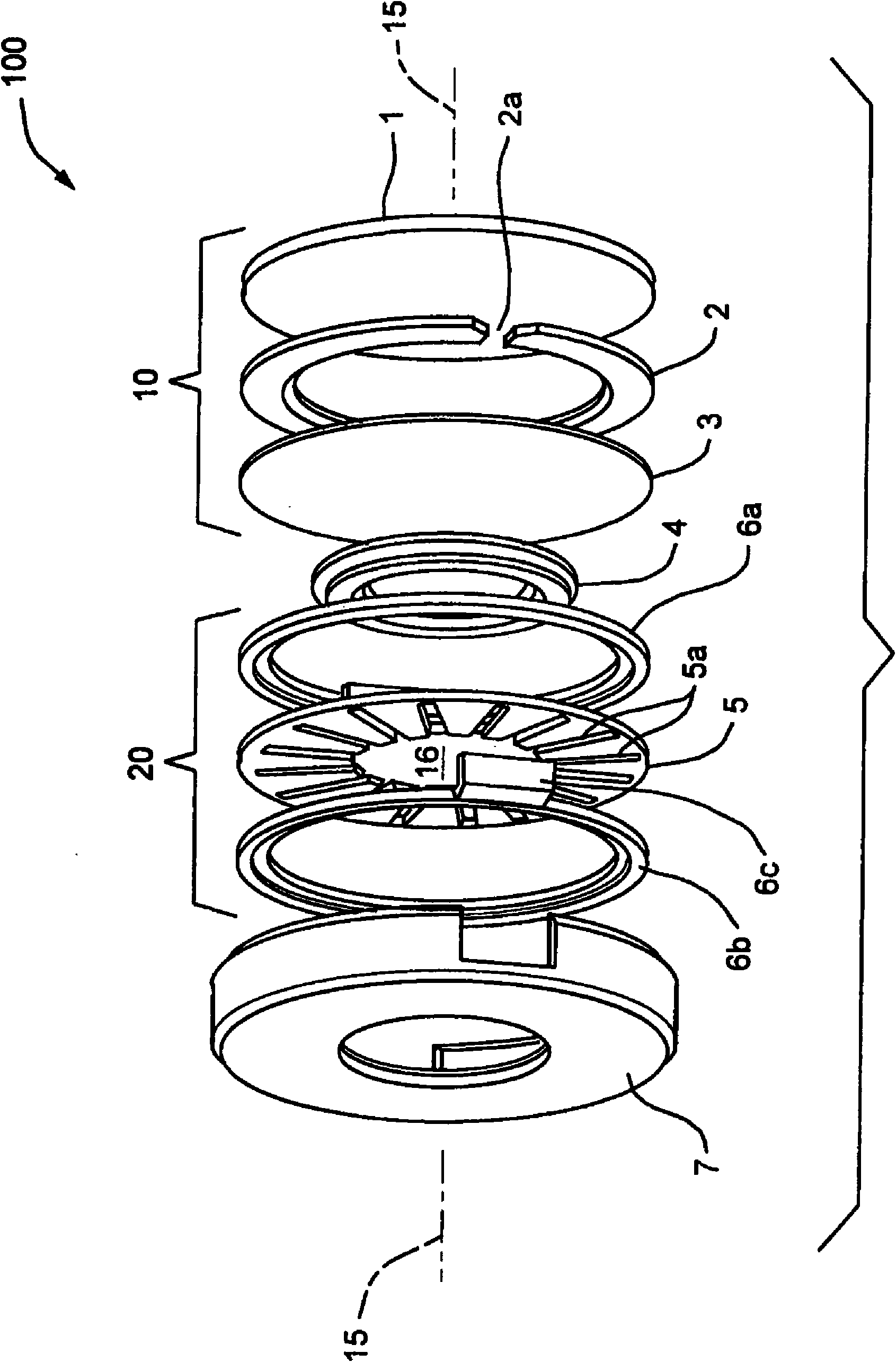
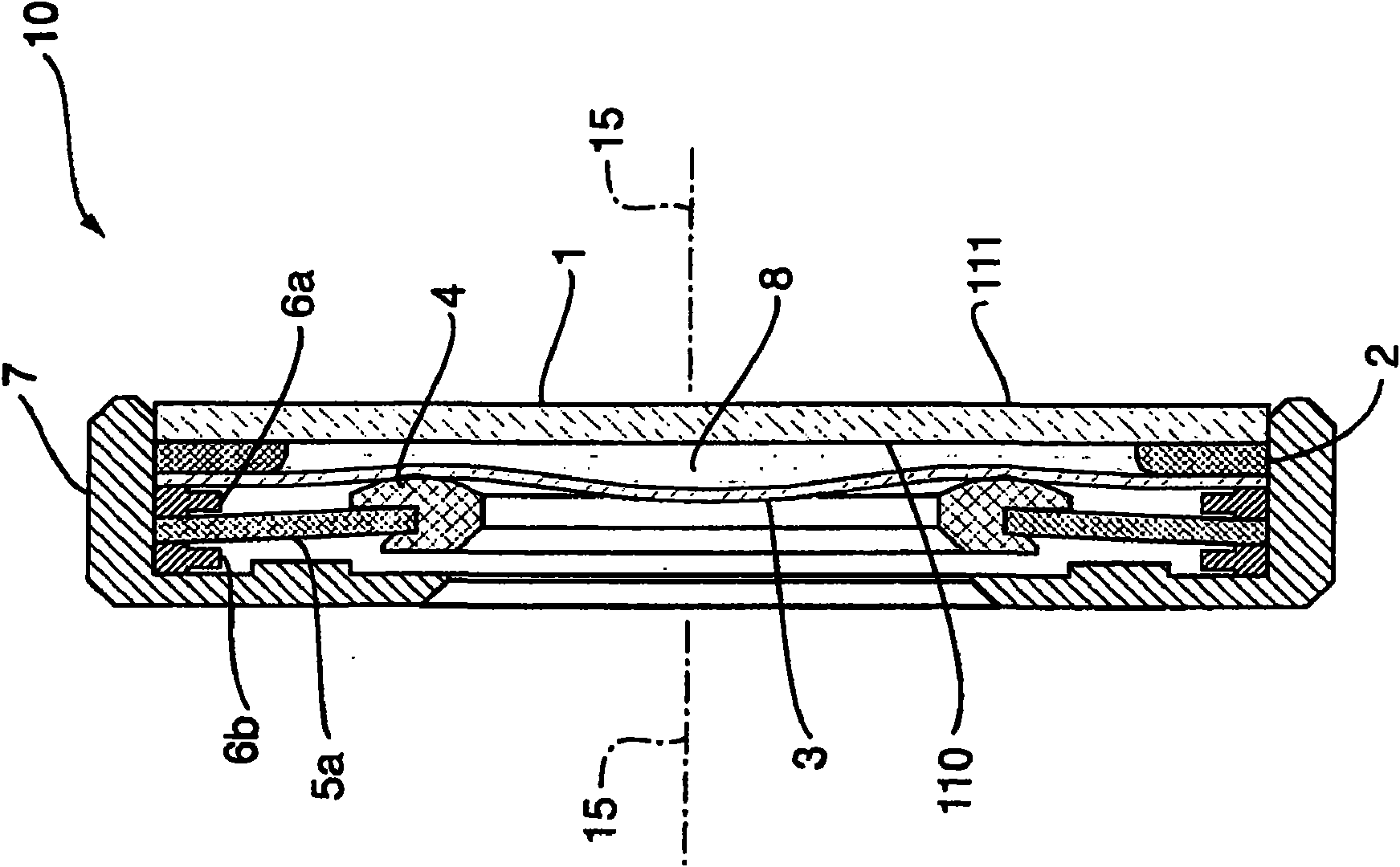
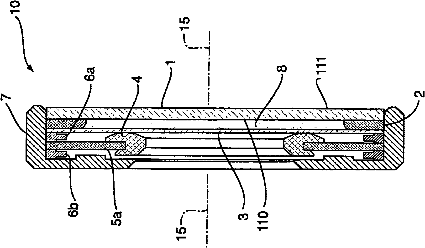
[0197] well-founded Figure 6 The focusing device used for focusing of the structure shown and the focusing device is installed on a model IT5000 Image Engine available from Hand Held Products, with a 5.88mm focal length, 6.6F# and a micro 36-inch micro fixed best focal length three-lens imaging lens combination. A driver from ARTIFICIAL MUSCLE INCORPORATED ("AMI") was used, based on the design of the MLP-95 or MSP-95 autofocus elastomer driver available from AMI. After constructing the focusing element, various voltages were applied to the flexible electrodes of the actuation device, the results are summarized in Table C below:

[0198] Form C

[0199] Voltage (volts)

Distance between drive unit (20) and pressure element (4)

move

best focus distance

0

0

36″

600

0.025mm

8″

790

0.050mm

6″

896

0.075mm

3″

[0200] It has been found that large variations in the opt...


PUM


Abstract

An apparatus for use in a lens assembly, the apparatus comprising a deformable lens element having an axis and a deformable surface, at least part of which transmits image forming ligth rays, and a force imparting structural member disposed to impart a force to said deformable surface, wherein the apparatus is adapted so that said force imparting structural member is capable of imparting at least one of a pushing force or a pulling force to the deformable surface.

Description

[0001] Cross References to Related Applications [0002] This PCT application claims priority to U.S. Patent Application No. 60 / 875,245, entitled "Focus Module and Components With Actuator Polymer Control," filed December 15, 2006; 2007 Priority of U.S. Patent Application No. 60 / 901,036, filed July 18, 1999, entitled "VariableLens Elements And Modules"; U.S. Patent Application No. 11 / , filed July 23, 2007 781,901, priority of U.S. Patent Application No. 11 / 781,901, entitled "Focus Module and Components With Actuator Polymer Control," which claims U.S. Patent Application No. 60 / 875,245 , and 11 / 897924, filed August 31, 2007, entitled "Apparatus and Method Comprising Deformable Lens Element," and U.S. Patent Application No. 11 / 897924 claims priority to said US Patent Application No. 60 / 875,245 and US Patent Application No. 60 / 901,036. All of the above patent applications are hereby incorporated by reference in their entirety. technical field [0003] The present invention re...

Claims


Application Information

Patent Timeline
Patent Type & Authority Applications(China)
IPC IPC(8): G02B3/14G02B26/08G02B7/38G02B26/06G02B15/00G06K7/10H04N5/232
CPCG02B7/028G02B15/00H04N5/23212H04N5/2254G02B7/38G02B3/14G02B26/06G02B26/0875
Inventor 元军·P·王晨·冯威廉·H·海温斯李建华
Owner HAND HELD PRODS
Why Eureka
Try Eureka