Wiring method and manufacturing method of capacitive touch screen

A technology of a capacitive touch screen and a manufacturing method, which is applied in the direction of electrical digital data processing, input/output process of data processing, instruments, etc., can solve the problem of reducing the quality of touch screen products, high wire resistance of conductive films of wires, and color difference of two layers of conductive films. and other problems, to achieve the effect of good consistency of line resistance value, improve yield rate, and avoid chromatic aberration

Active Publication Date: 2010-01-27
SHENZHEN LAIBAO HI TECH
View PDF0 Cites 27 Cited by
  • Summary
  • Abstract
  • Description
  • Claims
  • Application Information

AI Technical Summary

Problems solved by technology

Since the transparent conductive films of the two sets of wires must be made separately, it will cause color differences between the two layers of conductive films and reduce the product quality of the touch screen;
[0004] 2. Since the conductive film material of the wire is made of transparent material, the film layer is relatively thin, and the bridging film layer above the intersection point of the two sets of wires is prone to disconnection, resulting in partial wire disconnection of the wire and reducing the product yield;
[0005] 3. The conductive film wire resistance of the wire is high, which reduces the performance of the touch screen

Method used


Image

  • Wiring method and manufacturing method of capacitive touch screen
  • Wiring method and manufacturing method of capacitive touch screen
  • Wiring method and manufacturing method of capacitive touch screen

Examples


Embodiment Construction

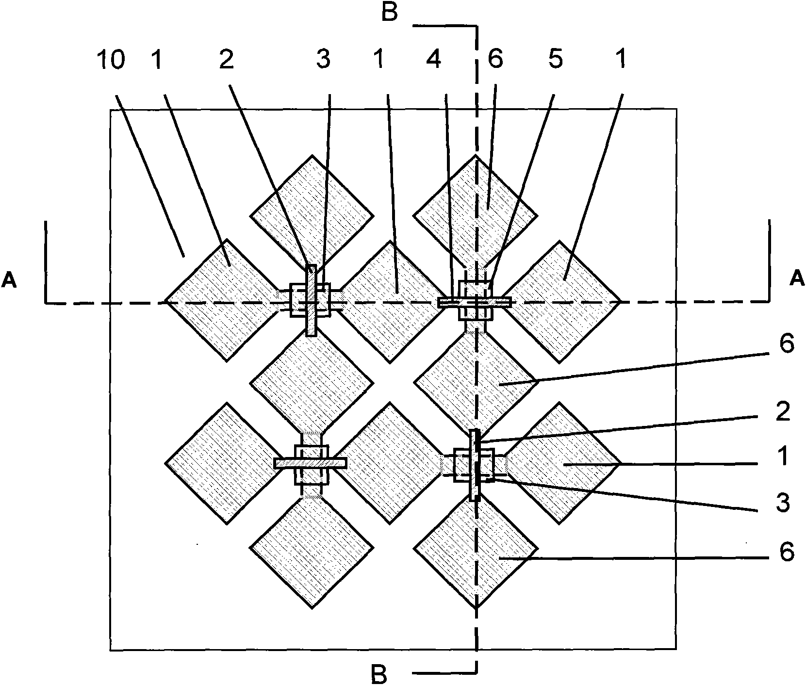
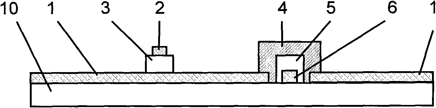
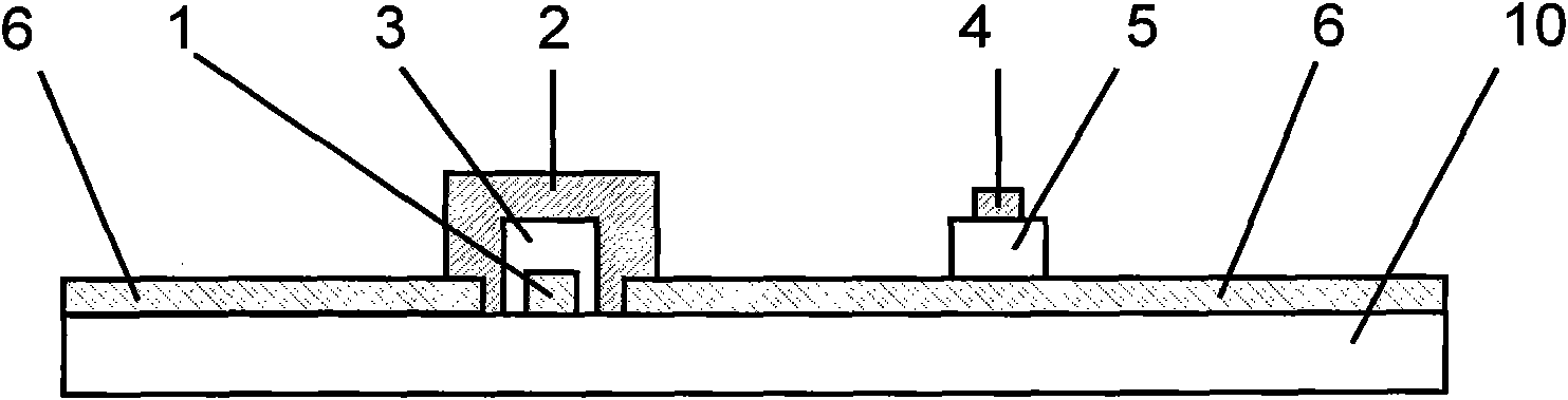
[0035] Such as figure 1 , figure 2 , image 3 As shown, the wiring of the capacitive touch screen of the present invention includes transparent conductive films 1,6, insulating films 3,5 and surface resistance lower than transparent conductive films 1,6 of two groups of wires arranged on the substrate 10 along the X and Y directions. Bridging membranes2,4.

[0036] The structure of the transparent conductive film 1 in the X direction at the intersection with the transparent conductive film 6 in the Y direction includes continuous connections and bridge connections. connection, continuous connection, bridging connection, continuous connection, continuous connection, bridging connection" or "continuous connection, bridging connection, bridging connection, continuous connection, bridging connection, bridging connection", etc.), or irregular arrangement, all The object of the present invention can be realized.

[0037] The structure of the transparent conductive film 6 in the...


PUM


Abstract

The invention relates to a wiring method and a manufacturing method of a capacitive touch screen, wherein the wiring method comprises the step of arranging two groups of wire transparent conducting films in X and Y directions, an insulating film and a bridging film on a basal plate, wherein the surface resistance of the bridging film is lower than the surface resistance of the transparent conducting films, an intersection structure of the transparent conducting films in the two directions comprises continuous connection and bridging connection, wherein the continuous connection structure is a continuation of transparent conducting film material at two sides of the intersection point, and the bridging connection structure has the structures that the transparent conducting film in X or Y direction is continuously connected and positioned on the basal plate at the intersection point, the transparent conducting film in the other direction is disconnected at the intersection point, the insulating film is covered on the transparent conducting films that are continuously connected at the intersection part, and the bridging film stretches over the transparent conducting films that are continuously connected at the intersection point and is covered on the insulating film and connected with the transparent conducting film disconnected at the intersection point; and the method comprises the step of manufacturing two groups of wire conducing film, the insulating film and the bridging film. The invention can avoid color difference and improve the sensitivity, the standard ratio and the quality of the touch screen.

Description

technical field [0001] The present invention relates to a touch screen wiring, and also relates to a manufacturing method of the touch screen wiring, in particular to a capacitive touch screen wiring and a manufacturing method thereof. Background technique [0002] The wiring of the touch screen includes two sets of wires crossing in the X direction and the Y direction. The existing touch screen wiring structure has the following defects: [0003] 1. The two groups of wires in the X direction and the Y direction intersect in space. In the manufacturing process, it is necessary to make a bottom group of conductive films first, then make an insulating film, and then make an upper group of conductive films. Since the transparent conductive films of the two sets of wires must be made separately, it will cause color differences between the two layers of conductive films and reduce the product quality of the touch screen; [0004] 2. Since the conductive film material of the wire...

Claims


Application Information

Patent Timeline
Patent Type & Authority Applications(China)
IPC IPC(8): G06F3/044
Inventor 李绍宗王士敏朱泽力郭志勇钟荣苹
Owner SHENZHEN LAIBAO HI TECH
Why Eureka
Try Eureka