Pneumatic tire

A technology for pneumatic tires and treads, applied to tire parts, tires, wheels, etc., can solve problems such as insufficient countermeasures, and achieve the effect of preventing sharp decline

Inactive Publication Date: 2010-01-27
THE YOKOHAMA RUBBER CO LTD
View PDF2 Cites 3 Cited by
  • Summary
  • Abstract
  • Description
  • Claims
  • Application Information

AI Technical Summary

Problems solved by technology

Even when the sealant is impregnated into the sponge, a non-crosslinked sealant is usually used, so the flow during driving is improved to some extent, but it is not a sufficient countermeasure

Method used


Image

  • Pneumatic tire
  • Pneumatic tire
  • Pneumatic tire

Examples


Embodiment

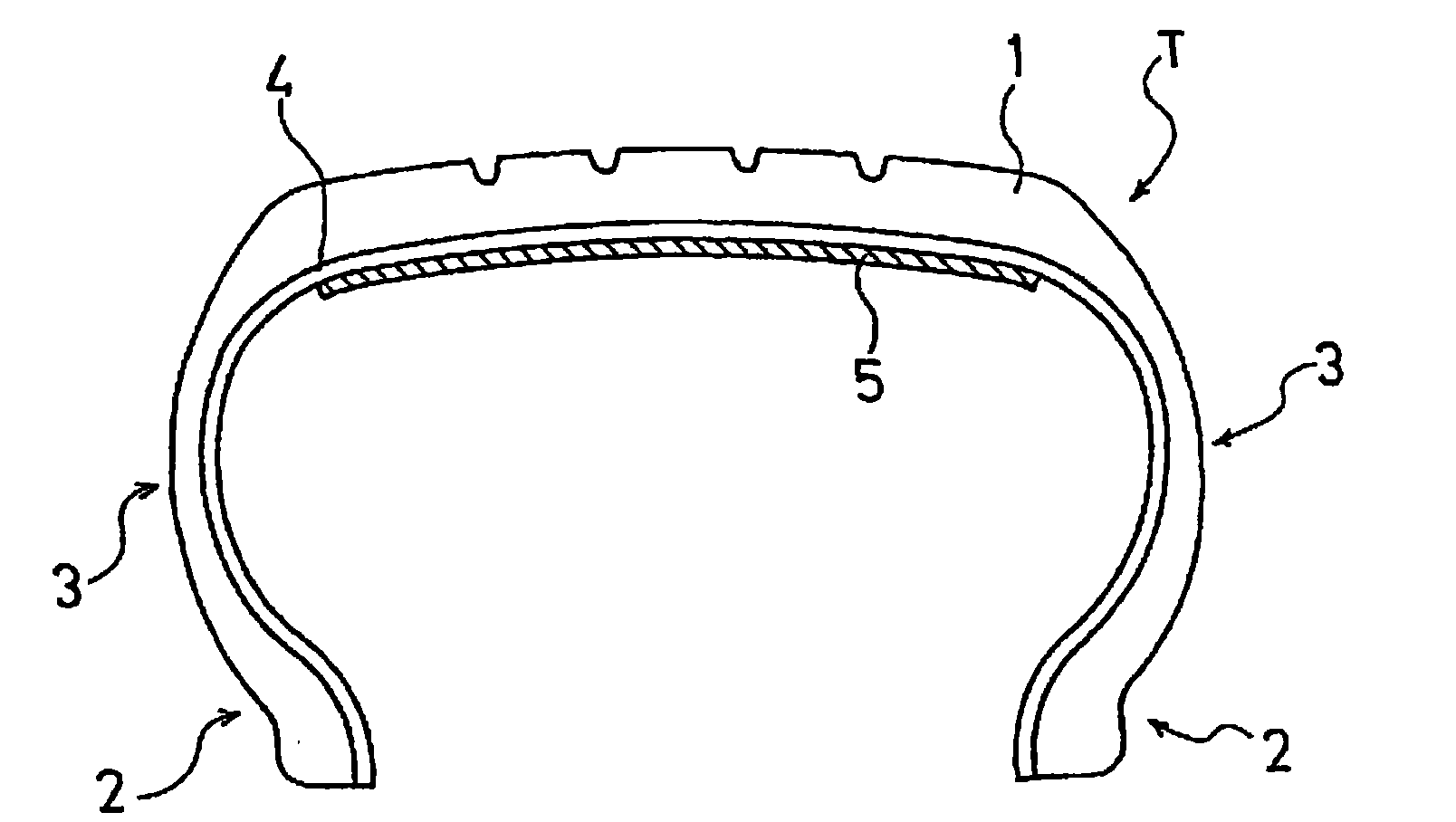
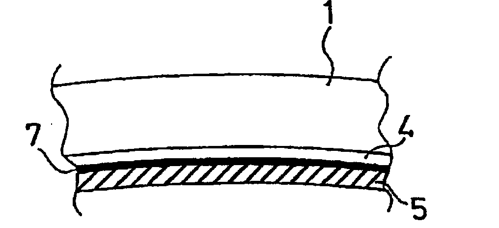
[0044] Set tire size to 205 / 65R15 and tire construction to figure 1 With the structures shown, a conventional tire (corresponding to Example 1 in JP-A-2003-183623 ) and a tire of the present invention using an adhesive sealant as the puncture prevention layer were manufactured. In addition, in each tire, the thickness of the puncture prevention layer was set to 5 mm, and as the gel sheet of the tire of the present invention, a gel sheet mainly composed of ethylene-styrene copolymer (penetration: 60 , Oscar C-type hardness: 15, compression permanent strain rate 8%).

[0045] After assembling each tire on the rim, fill it with an air pressure of 210kPa, and run it continuously at a speed of 90km / h for 8 hours through an indoor roller testing machine, and then investigate the left and right ends of the puncture prevention layer on the inner surface of the tire after running. Offset (movement) condition.

[0046] As a result, in the conventional tire, the width of the puncture p...


PUM

PropertyMeasurementUnit
thicknessaaaaaaaaaa
thicknessaaaaaaaaaa
penetrationaaaaaaaaaa

Abstract

The invention provide a pneumatic tire, the uniformity of which is improved although a puncture-preventing layer is arranged on the inner side of a tread portion. A gel sheet (5), which is so made of a silicone compound, an urethane compound, a styrene compound or an ethylene compound as to have a penetration of 50 or more, after set, and an ASKER C hardness of 40 or less, is arranged as a puncture-preventing layer on the inner side of an inner liner (4) in the region corresponding to the tread portion (1).

Description

technical field [0001] The present invention relates to a pneumatic tire, and more specifically, to a pneumatic tire in which a puncture preventing layer is arranged inside a tread portion and uniformity can be improved. Background technique [0002] In order to ensure the safety of the vehicle when the tire hits a nail or the like during driving, many pneumatic tires have been proposed in which an adhesive sealant is arranged as a puncture prevention layer inside the tread portion, and when a puncture occurs due to a nail being hit, a pneumatic tire is proposed. When the nail is broken, the adhesive sealant is allowed to flow into the puncture hole after the nail is pulled out by centrifugal force, thereby avoiding a sudden drop in air pressure (for example, refer to Patent Document 1). [0003] However, in such pneumatic tires, due to the centrifugal force at high speed, the adhesive sealant flows inside the tire inner wall and concentrates in the central region in the tir...

Claims


Application Information

Patent Timeline
Patent Type & Authority Applications(China)
IPC IPC(8): B60C19/12B29C73/10B29L30/00
CPCB29C73/22B29D2030/0695B29L2030/00B60C19/122B29D30/0685Y10T152/10684
Inventor 关口巧
Owner THE YOKOHAMA RUBBER CO LTD
Why Eureka
Try Eureka