
Filter

A technology of filters and filter chambers, applied in the field of filters, can solve problems such as liquid path failures, reduced quantitative sampling accuracy, and blockage of liquid path components

Active Publication Date: 2010-02-03
SHENZHEN MINDRAY BIO MEDICAL ELECTRONICS CO LTD
View PDF0 Cites 3 Cited by
  • Summary
  • Abstract
  • Description
  • Claims
  • Application Information

AI Technical Summary

Problems solved by technology

However, in actual use, it has been found that if a filter with higher precision (the gap of the filter element is smaller) is used, due to the negative pressure inside the filter, many bubbles will be generated on the inner wall of the filter element when the filter is working, and these bubbles will gather to a certain level. After a certain degree, it will enter the pipeline with water (such as the quantitative sampling pipeline of the biochemical analyzer), which will reduce the accuracy of quantitative sampling, and then affect the test performance of the entire biochemical analyzer.
In order to avoid a large number of air bubbles, it is necessary to use a low-precision filter, but the water filtered by this filter often contains large impurity particles, which will block the precise liquid circuit components and cause liquid circuit failures

Method used


Image

  • Filter
  • Filter
  • Filter

Examples


Embodiment Construction

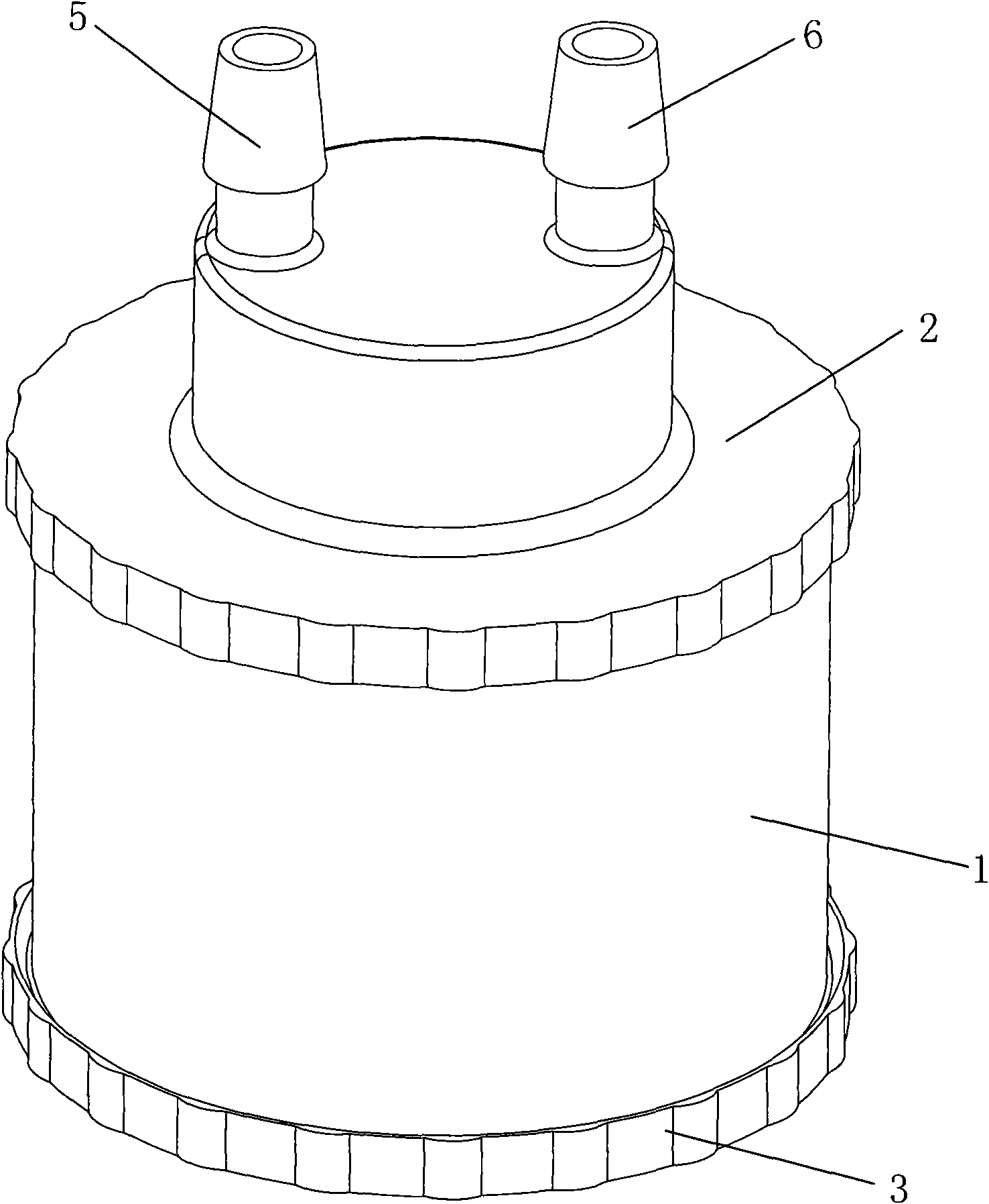
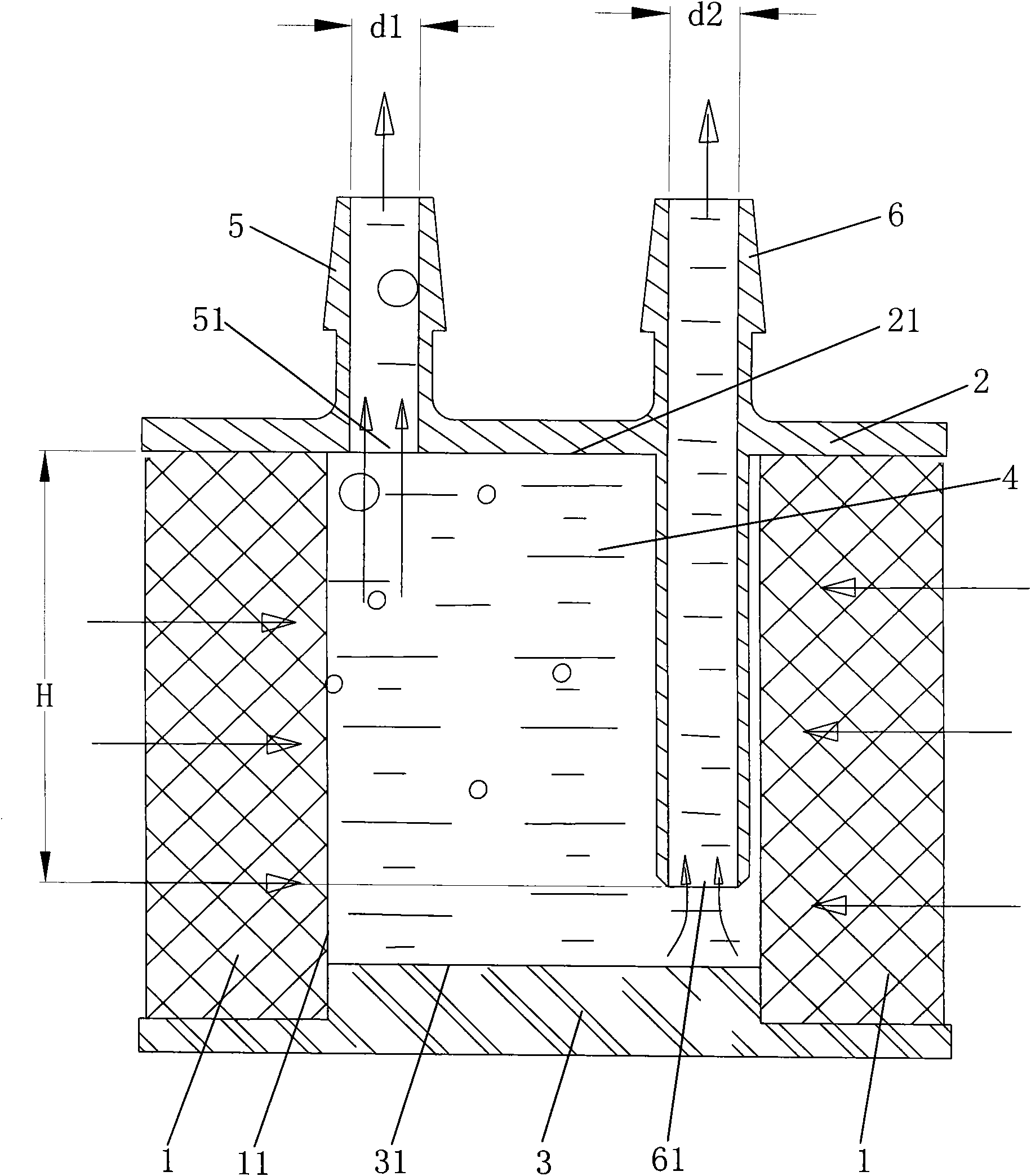
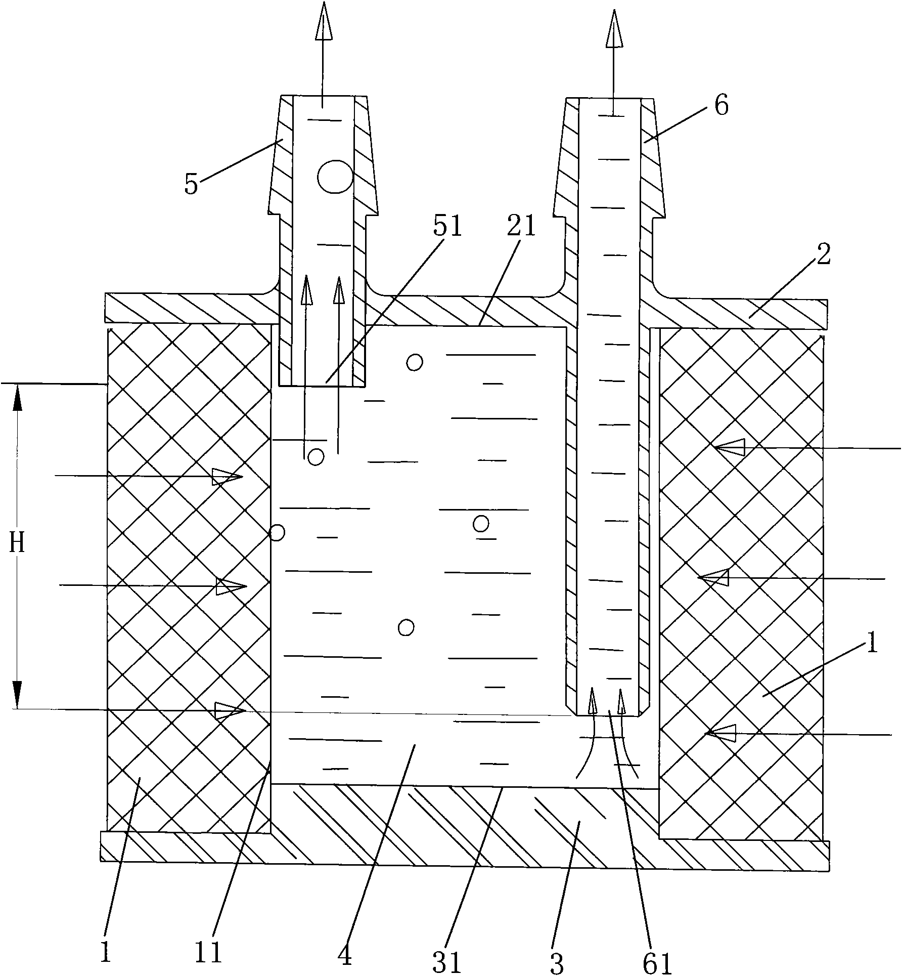
[0018] Such as figure 1 and figure 2 As shown, the filter in this embodiment includes a filter element 1 , a top cover 2 and a bottom cover 3 . The filter element 1 is a cylindrical structure penetrating up and down, the top cover 2 and the bottom cover 3 are respectively fixed on the top and bottom of the filter element 1, and the inner wall surface 11 of the filter element 1, the inner wall surface 21 of the top cover 2 and the bottom cover 3 The inner wall surface 31 of the filter cavity 4 is surrounded. The filter element 1 is provided with a plurality of slits for introducing the fluid to be filtered into the filter cavity, and the fluid is a mixture of gas and liquid. The top cover 2 is provided with a first discharge pipe 5 and a second discharge pipe 6, the first discharge pipe 5 is vertically fixed on the top cover 2, the first discharge pipe 5 communicates with the filter chamber 4, and the first discharge pipe 5 is connected to the filter chamber 4. The bottom o...


PUM


Abstract

The invention discloses a filter. The filter comprises a filter core, a top cover, a bottom cover, at least one first exhaust pipe and at least one second exhaust pipe, wherein the filter core is provided with a gap for passing through fluid to be filtered; the top cover and the bottom cover are respectively fixed to the upper part and the lower part of the filter core; the inner wall surface of the filter core, the inner wall surface of the top cover and the inner wall surface of the bottom cover enclose a filter cavity; the first exhaust pipe is communicated with the filter cavity and is arranged on the top cover; the first exhaust pipe is provided with at least one first inlet for fluid flowing in; the second exhaust pipe is communicated with the filter cavity and is arranged on the topcover or the bottom cover; the second exhaust pipe is provided with at least one second inlet for fluid flowing in; and the first inlets are all positioned above the second inlets in a direction of gravity. The filter not only can ensure filter accuracy, but also can separate two kinds of fluid.

Description

technical field [0001] The invention relates to a filter for filtering fluid in a biochemical analyzer. Background technique [0002] In the water inlet pipeline system of the biochemical analyzer, in order to prevent impurities from entering the pipeline system and causing blockage and failure of various components in the system, most water inlet filters are used to filter the water entering the pipeline to filter out the impurity particles in the water. However, in actual use, it has been found that if a filter with higher precision (the gap of the filter element is smaller) is used, due to the negative pressure inside the filter, many bubbles will be generated on the inner wall of the filter element when the filter is working, and these bubbles will gather to a certain level. After a certain degree, water will enter the pipeline (such as the quantitative sampling pipeline of the biochemical analyzer), which will reduce the accuracy of quantitative sampling, and then affec...

Claims


Application Information

Patent Timeline
IPC IPC(8): B01D35/01B01D29/33
CPCB01D19/0042G01N1/10B01L3/502723B01D29/114B01D2201/043B01D2201/0453B01D2201/46
Inventor 张鹏石学园高再兴许智
Owner SHENZHEN MINDRAY BIO MEDICAL ELECTRONICS CO LTD
Learn More