

Crease type crash energy absorption box
A technology of collision energy absorption and concave angle, which is applied to bumpers and other directions, can solve the problems of low load uniformity coefficient of specific energy absorption rate, etc., and achieve the effect of low load uniformity coefficient, convenient processing and low production cost.
- Summary
- Abstract
- Description
- Claims
- Application Information
AI Technical Summary
Problems solved by technology
Method used
Image

Examples
Embodiment 1
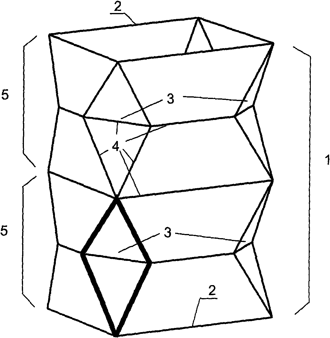
[0032] Example 1: figure 1 An embodiment of a crash box with a rectangular equal cross-section.
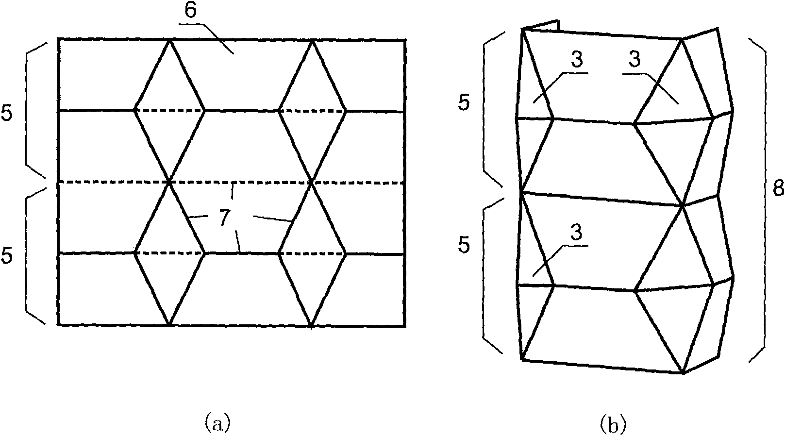
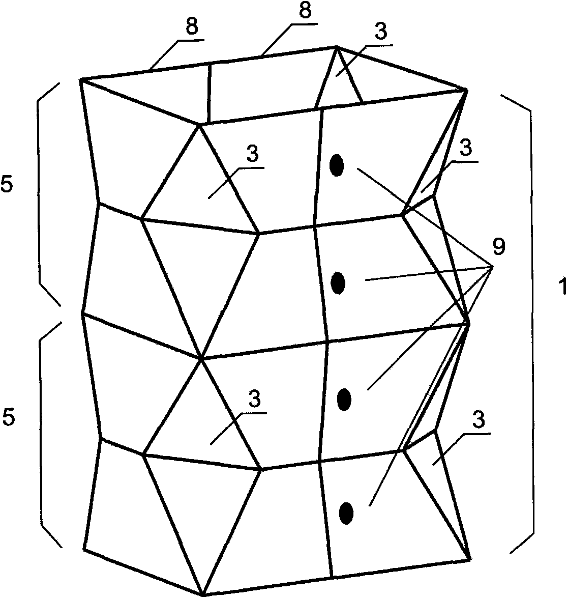
[0033] The so-called crash box 1 with a rectangular equal section means that the section 2 of 1 is rectangular. With the second process, the box is assembled from two identical half-shells. figure 2 (a) 6 is the planar expansion of the half-shell of the rectangular equal-section crash box, figure 2 (b) 8 is a schematic diagram of the half-shell after compression molding, which is used to elaborate figure 1 The shape design of the crash box 1 with a rectangular equal section. In the present invention, the crash box adopts a modular form, wherein the module 5 refers to the smallest unit that can represent the shape of the crash box. Crash boxes of different lengths can be obtained by superimposing several modules in the axial direction. 6 describes the unfolded shape of the half-shells of the two modules, and their lengths in the axial direction do not have to be the same. Th...
Embodiment 2
[0035] Example 2: Figure 4 An embodiment of a crash box with a triangular equal section.
[0036] Using the second process, the box is assembled from three identical one-third shells. Figure 5 (a) 12 is the plane expansion of one-third of the triangular equal-section crash box, Figure 5 (b) 13 is a schematic diagram of the one-third shell after compression molding, which is used to elaborate Figure 4 The shape design of the crash box 10 with a triangular equal section. The module 11 refers to the smallest unit that can represent the shape of the crash box. Crash boxes of different lengths are obtained by superimposing several modules in the axial direction, and 12 describes the shape of one-third shells of the two modules after unfolding, and the length of each module in the axial direction does not have to be the same. According to the definition of crease lines in Example 1, the same mold pressing is performed on 12 in this example, and finally a formed third shell 1...
Embodiment 3
[0037] Example 3: Figure 6 An embodiment of a hexagonal crash box with equal cross-section.
[0038] Figure 6 Middle 14 is the collision absorbing box of hexagonal equal section. During the forming process, six identical six-sixth shells are pre-pressed and then assembled, or two half-shells are pre-pressed and identical, and then assembled. The implementation method is the same as the above two embodiments.
PUM
 Abstract
Description
Claims
Application Information