Storage device for binding wire of a cording machine

A technology of accumulating device and strapping device, applied in the field of accumulating device

Active Publication Date: 2015-06-10
ANDRITZ AG
View PDF9 Cites 0 Cited by
  • Summary
  • Abstract
  • Description
  • Claims
  • Application Information

AI Technical Summary

Problems solved by technology

[0006] The relatively high dynamic forces generated by this forward feed speed of up to 200 m / min cause further problems when the wire or the drum on which the wire is wound is accelerated or braked.

Method used


Image

  • Storage device for binding wire of a cording machine
  • Storage device for binding wire of a cording machine
  • Storage device for binding wire of a cording machine

Examples


Embodiment Construction

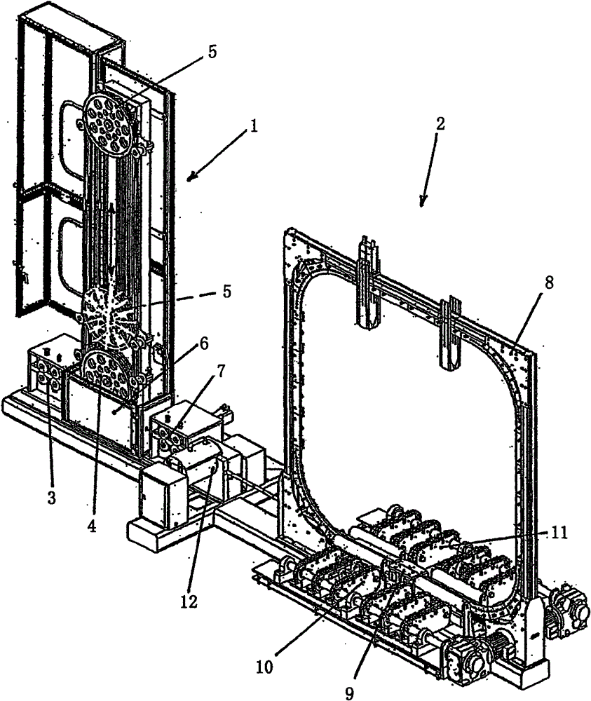
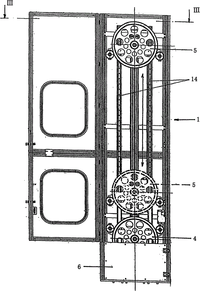
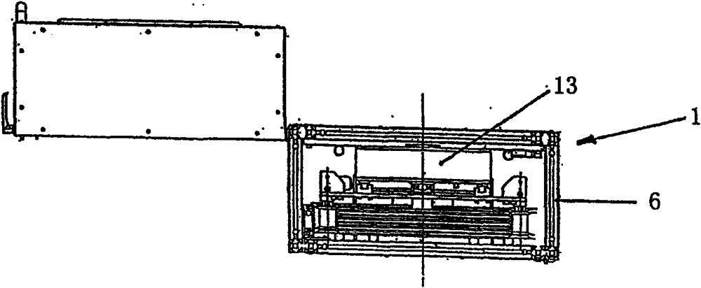
[0043] figure 1 A binding machine for binding pulp bales with galvanized steel wires is shown, which mainly includes an accumulating device 1 and a binding device 2 . The binding wires for binding the pulp bales are supplied to the left side from a drum, tower or similar device not shown here, by being extracted from the rollers with the first drive 3 to the Figure 1-3 The accumulation device of the first embodiment shown in . The binding wire, not shown in the figure, is then wound several times (three times in this embodiment) around the two roller sets 4 , 5 , after which the second drive 7 feeds the binding wire to the binding frame 8 . The roller sets 4, 5 each comprise circular discs arranged coaxially close to each other, which can pivot independently of each other and which have grooves in their circumferential surfaces to guide the binding wire.

[0044]In the binding frame 8, the binding wire is wound once in an anti-clockwise direction at an angle of slightly mor...


PUM


Abstract

An accumulator device (1) for the tying wire of a tying machine used in pulp production has a drive (3) at the inlet to the accumulator device and another drive (7) at the outlet from the accumulator device. By means of the accumulator device (1) according to the invention and the two drives (3, 7), it is possible to store the entire length of wire required for one tying cycle temporarily and then to remove the wire from the accumulator for the tying cycle. In this way, a dynamic accumulator volume is created for the tying wire in the accumulator device (1).

Description

technical field [0001] The invention relates to an accumulating device for bundling wires in a binding machine, in particular for pulp production, the accumulating device having an inlet to the accumulating device and an outlet leaving the accumulating device and a drive for driving the bundled wires device. [0002] Furthermore, the invention relates to a method for feeding a binding device, in particular for pulp production, with binding wires via an accumulation device, wherein the binding wires are fed into said accumulation device through an inlet and output from said accumulation device to the binding device through an outlet. Background technique [0003] Strapping machines are used in the finishing section of packaging in pulp production. Here, pulp bales (wrapped in pulp boards or unwrapped), pulp stacks (3-4 bales totaling about 1 metric ton) or pulp units (2 pulp stacks) are bound together with galvanized steel wire. When pulp bales are mentioned below, it may m...

Claims


Application Information

Patent Timeline
Patent Type & Authority Patents(China)
IPC IPC(8): B65B13/18
CPCB65B13/184B65H20/34B65H51/20
Inventor 乌特·菲格韦尔特·弗里茨尔
Owner ANDRITZ AG
Why Eureka
Try Eureka