
Test method of electronic device

The technology of an electronic device and testing method is applied in the direction of electronic circuit testing, marginal circuit testing, measuring devices, etc., which can solve the problems of beautiful space occupied by test pins, redundant test pins, and overall aesthetic defects, and achieve changes in circuit wiring, The effect of increasing the board area and saving time

Inactive Publication Date: 2010-02-03
LITE ON ELECTRONICS (GUANGZHOU) LTD +1
View PDF0 Cites 0 Cited by
  • Summary
  • Abstract
  • Description
  • Claims
  • Application Information

AI Technical Summary

Problems solved by technology

For electronic devices that do not need to install batteries, the test pins have to open test holes on the shell, but this will bring defects in the overall appearance
However, no matter what, the test pins are redundant and useless for users, and the test pins not only take up space but also have aesthetic problems

Method used


Image

  • Test method of electronic device
  • Test method of electronic device
  • Test method of electronic device

Examples


Embodiment Construction

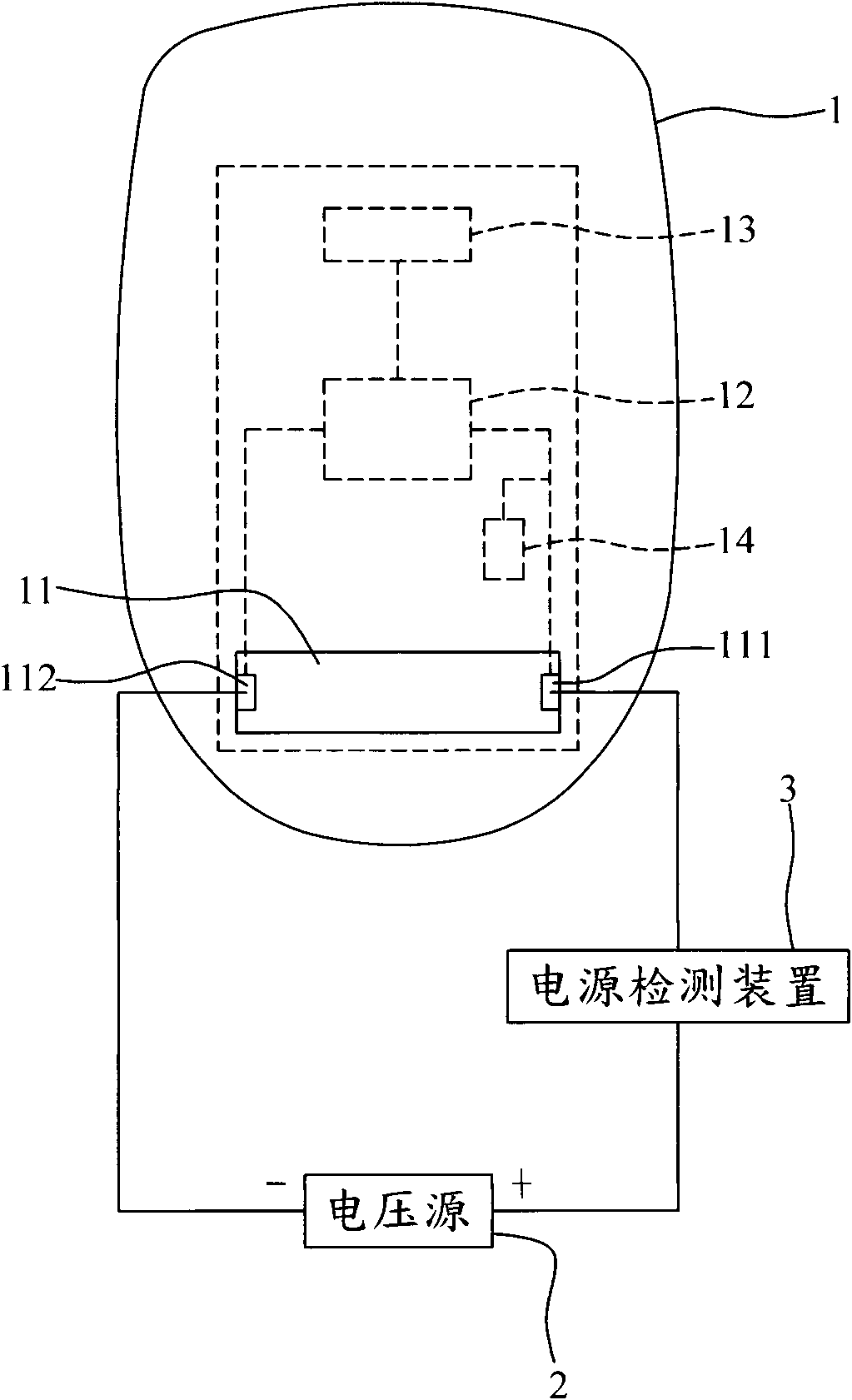
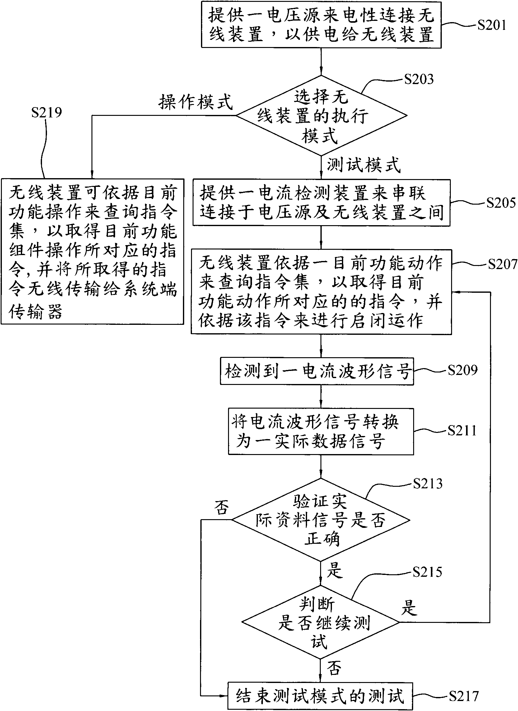
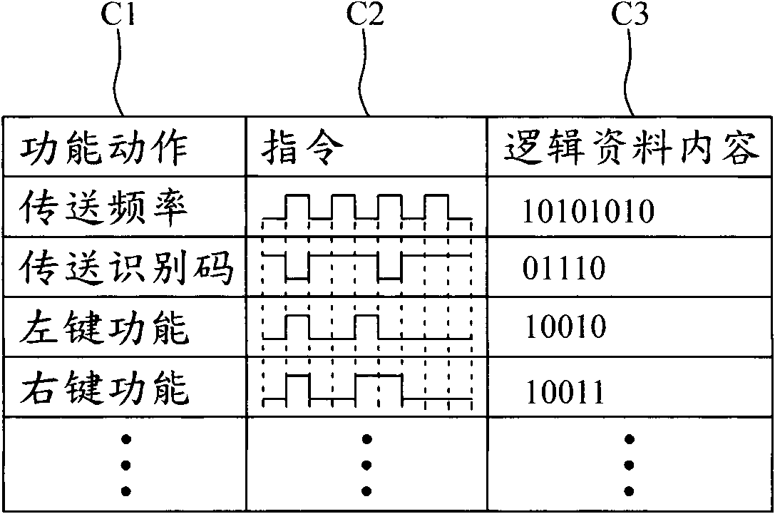
[0020] The present invention is through the design of the control unit of the electronic device (such as: wireless mouse, wireless keyboard, wireless remote control, etc.), as long as the external voltage source is input through the existing power transmission path (power line), it can be tested When pressing or operating a functional component in the mode, the control unit will not send a relative operation signal to the host, but will relatively affect the initial current waveform of the external power supply voltage, so as to test each functional component. Among them, different current change waveforms are generated for different functional components, and become test data signals of different functional components. In addition to supplying power, the power transmission path can also be used as a path for transmitting test data signals at the same time. In addition, the present invention directly uses the current change waveform transmitted by the power line of the electro...


PUM


Abstract

The invention relates to an electronic device, comprising a first power supply contact, a second power supply contact and a control unit; wherein, the first power supply contact is electrically connected with the positive terminal a voltage source, the second power supply contact is electrically connected with the negative terminal the voltage source, and the control unit is electrically connectedwith the first power supply contact and the second power supply contact, thus forming a signal transmission path and receiving power supply of the voltage source. When the control unit is executed ina test mode, the control unit completes open and close operation according to instruction in a preset instruction set, thereby changing a current waveform signal transmitted in the signal transmission path. Thus, the aim of convenient test and high test efficiency is achieved.

Description

technical field [0001] The invention relates to an electronic device and a testing method thereof, in particular to an electronic device and a testing method thereof which use a current waveform signal transmitted by a power line of the electronic device as a test data signal. Background technique [0002] In order to ensure the quality and stability of the electronic device, the testing and verification of the electronic device has become an indispensable process in the production stage. Before leaving the factory, functional components with specific functions (such as wireless modules, keys, scrolls, and touch pads) on the electronic device must be confirmed to be able to operate normally. That is to say, when a user presses or operates a functional component, the manufacturer needs to ensure that the control unit of the electronic device can transmit correct digital signals to the host through wireless or wired means, so as to maintain the quality and stability of the ele...

Claims


Application Information

Patent Timeline
Patent Type & Authority Applications(China)
IPC IPC(8): G01R31/00G08C19/02G06F11/22
CPCG01R31/3004
Inventor 严道成
Owner LITE ON ELECTRONICS (GUANGZHOU) LTD
Learn More